Before you buy a double-layer roll forming machine, map the equipment that each profile needs. Check decoiling, feeding, drive, forming, cutoff, PLC control and stacking separately.
Two forming levels alone do not tell you which devices are shared, how the line changes profiles, or whether both can run at once. You need a layout that follows each coil through to a finished stack, plus written module quantities and an operating sequence for the quoted configuration.
Map the two profiles to a line layout
Start with two complete material routes on the same dimensioned layout. Label your drawings Profile A and Profile B, then follow each one from coil loading to the place where you remove the finished stack. A drawing of the machine base alone leaves out the connections that determine whether the line fits your plant.
Keep strip width separate from finished cover width. The first describes the material entering the rolls; the second describes the coverage of the formed panel. Put both on the inquiry so that a correct-looking cross-section does not hide a mismatch in the coil you intend to buy.
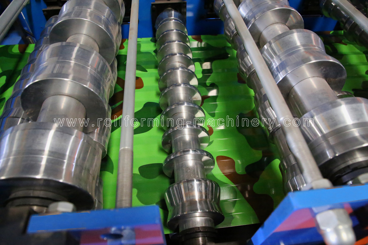
Corrugated sheet passing through the forming rolls.
Extend the layout beyond the mill. Show coil storage and loading access, the control position, maintenance access, the longest panel you plan to make and the route for removing a stack. Request dimensions in mm or m and identify which unit applies. The usable footprint includes these working areas, not just the steel frame.
BMS describes its double-layer roll forming machine for Trimrib and corrugated sheets with two profile systems on one base and a tilt stacker. Compare that arrangement with your two marked routes. Ask BMS to identify the actual infeed, cutting and discharge devices for the version being quoted, rather than filling in those connections from the product name.
Identify shared and independent modules
Ask the supplier to complete the checklist for the quoted line. “Included” tells you what you are buying. “Independent” tells you whether a profile has its own physical equipment. “Confirm” identifies the operating detail you still need. A device can be included yet shared, and separate controls can still depend on a common motor or hydraulic unit.
Keep “not included,” “shared,” “dedicated” and “to be confirmed” separate in the supplier’s reply. Do not accept a blank cell as an answer. In BMS’s published workflow, exit racks and an automatic tilt stacker are alternatives; your offer should name and price the discharge arrangement you will receive.
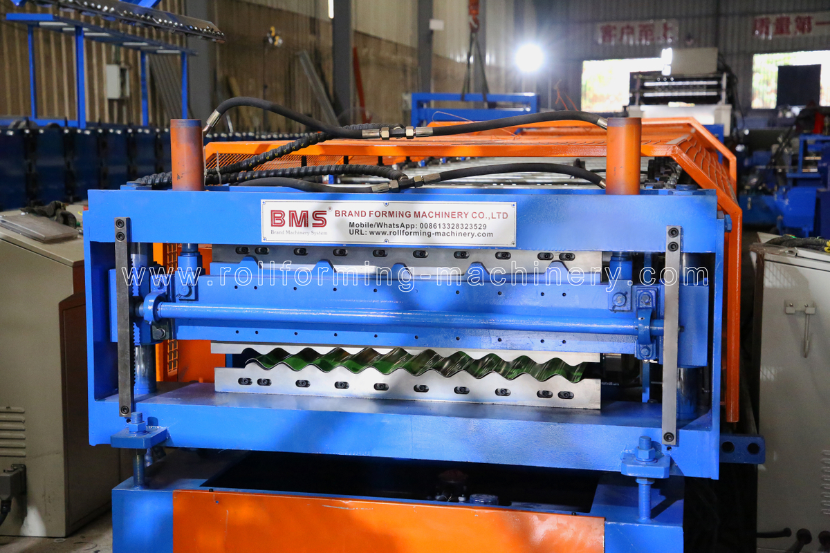
Profiled openings at two heights in a BMS cutoff assembly.
Inspect the cutoff at more than blade level. Two profile-shaped openings do not settle whether the shears have separate actuators, a common hydraulic source or a linked cutting cycle. Ask for the cutting assembly layout and the supplier’s explanation of how each profile is cut. Leave the shared-cutoff question open until that configuration is defined.
Separate hardware, control and service boundaries
- Drive allocation. A separate motor identifies one part of the drive. Also trace the gearbox, chain or other transmission and any selection mechanism. Ask whether the inactive bank remains stationary in the permitted operating mode.
- Control allocation. One screen can select different profile recipes. That does not show how many motors or shears exist. Have the supplier connect each recipe, length sensor and output command to the relevant physical device.
- Service dependency. List the common parts needed by both products, such as a controller or hydraulic source if shared. Ask which spares you should hold and how loss of that device affects the production plan. Physical separation alone does not establish safe maintenance independence.
BMS’s double-deck roll forming machine range includes floor-deck lines, so confirm that the offer you shortlist is for your required roofing profiles. Match each forming bank and cutoff die to the corresponding roof-panel drawing before comparing drive, PLC and stacking scope.
Confirm the operating and changeover sequence
Confirm the permitted operating modes before planning output. Ask whether you can run only one profile at a time or whether the quoted line supports concurrent production. If simultaneous output matters, request a demonstration of both complete routes, including cutting and stacking. Running two forming banks without showing their discharge does not answer the question.
- Define the starting condition. Agree on the material, panel length, batch size and stack pattern for each profile. Record the last acceptable Profile A panel and the condition of the remaining coil and finished stack.
- Observe the material change. Have trained supplier staff show the specified changeover procedure. Record coil replacement or repositioning, strip clearance and threading work that the actual change requires. A demonstration starting with Profile B already threaded excludes that preparation time.
- Track mechanical and control changes. Note guide adjustment, drive selection, cutting setup, recipe selection and stacker alignment. Identify which changes are automatic and which require tools or manual adjustment. Ask who performs each task and what access is needed.
- Check the first finished B panel. Compare its cross-section, length and surface with the agreed drawing and material requirements. Include any adjustment and rejected startup panels before acceptable output resumes.
- Finish at repeatable output. Continue until Profile B produces the agreed repeat samples and stacks them correctly. Record elapsed time and startup scrap. Request the reverse B-to-A change as well; the two sequences need not involve identical work.
Keep this an observation of the supplier’s approved procedure. Your plant’s qualified team should assess guarding, access and energy-isolation arrangements for setup and maintenance. Do not treat a production-mode selector as permission to work on the other bank while equipment is running.
Use the whole production window
For one-profile-at-a-time operation, available shift time must cover A production, B production, coil changes, profile changes, interruptions and stack removal.
Compare accepted panels or accepted linear metres per stated shift, using the same product mix and panel lengths. Keep startup scrap and changeover minutes visible.
A forming-speed figure in m/min describes a rate under stated conditions. It does not tell you how many saleable panels the mixed shift delivers. Ask the supplier to state whether a quoted speed includes cutting stops and handling delays, then compare it with the measured finished output from the agreed trial.
Evaluate the tilt stacker and output path
Evaluate the tilt stacker as part of each profile’s complete output route. You need to know how the upper and lower exits reach it, how the panel is supported during transfer and where the completed stack leaves the line. Request an output-layout drawing for both selected profiles, including any adjustable guides or transfer equipment.
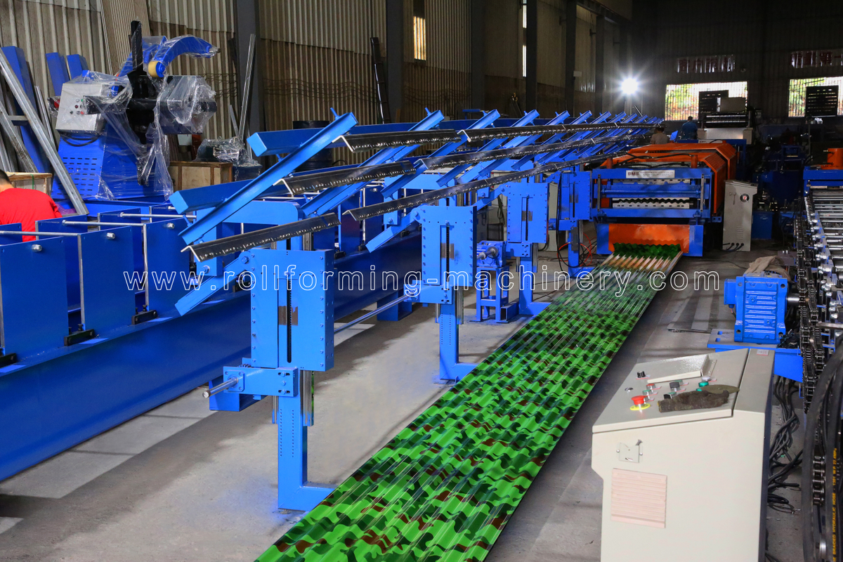
Tilt-stacker support arms beside corrugated sheet at the line exit.
- Exit height and transfer. Have the supplier show the route from each cutoff to the receiving supports. Identify what moves when you change profiles and whether additional tables or guides are required.
- Panel support and finish. Use the planned minimum and maximum finished lengths in the handling demonstration. Inspect the panel across transfer gaps, contact points and stacking movements for unwanted marking or shape changes.
- Stack pattern. Specify face up or face down, orientation of the laps, nesting or interleaving needs and sheet count per stack. Agree on the relevant length, width, height and mass limits in stated units.
- Full-stack removal. Mark the removal direction, handling equipment and working space on the layout. Ask whether production pauses, whether another receiving position is available and how the next stack begins.
- Batch control and recovery. Request a supplier-managed demonstration of counting, batch completion and an agreed stop/restart. Check how partly discharged panels and partly completed stacks are handled under the specified procedure.
Include the output equipment in any claim about running both profiles together. Two forming paths that reach one receiving position may need a defined alternating sequence or separate handling. Ask the supplier to show how panels are kept apart and counted if concurrent discharge is offered. Do not infer that arrangement from a photograph of the stacker.
Judge the finished stack as well as the individual sheet. Agree on alignment, acceptable surface condition and the stack pattern your next operation needs. Follow a trial batch through to stack removal: a panel leaving the cutter is an earlier endpoint than a stack ready for your handling team.
Define scope and acceptance in the purchase inquiry
Send the same input package to every supplier so you can compare complete offers. Attach the seven-module checklist and ask for quantities, shared connections, exclusions and options to be shown against a marked layout.
- Both drawings. Include revision numbers, finished cover widths, rib and lap details, length range and the tolerances that matter to your products.
- Production mix. State demand for each profile, typical order lengths, batch sizes, shift duration and how often you expect to switch products.
- Actual coil specifications. Give grade, coating, thickness and strip width in mm, plus coil mass in kg or t and coil inner/outer diameters in mm. State strength values in MPa where specified.
- Available footprint. Provide the plant layout with columns, access points, coil loading, service areas and stack-removal routes. State whether dimensions are in mm or m.
- Stacking pattern. Define panel orientation, nesting or interleaving, batch count, intended stack dimensions and the handling method after stacking.
- Changeover expectations. Specify the frequency and desired elapsed time, including coil, guide, cutter and stacker changes. Use the agreed last-good-A to repeat-good-B boundary.
- Electrical supply. Provide the plant’s verified voltage in V, frequency in Hz and number of phases. Ask the supplier to state connected load and required utilities for the complete quoted line.
- Commissioning scope. Request itemized installation, startup, operator training, language of manuals/training, spare parts and remote or on-site support. Allocate responsibilities, travel costs and trial material supply.
Agree on acceptance before the order
For your Mexico plant, involve the staff responsible for machinery safety before finalizing the layout. NOM-004-STPS-1999 addresses machinery risk assessment, operation and maintenance procedures, and protective devices in workplaces. Ask your qualified plant team to assess the proposed arrangement, including both forming levels, coil-loading access and stacker movement.
Use BMS’s metal roofing workshop planning guidance to separate plant preparation from the machine price. Assign floor preparation, power connection, coil loading and stack-removal space to the buyer or supplier in writing. Ask the supplier to itemize installation and training, and attach both drawings, the module allocation and agreed trial conditions to the purchase documents.
Frequently asked questions
Can the two profiles use different coil widths or thicknesses?
Treat them as separate material requirements. Ask the supplier to approve the range for each forming bank, feeder and cutoff, then show how any shared decoiler or transfer equipment handles both. A common base does not establish a common material range.
Can you service one bank while the other is producing?
Do not assume this is permitted. Separate motors or tooling do not establish separate safety or energy-isolation boundaries. Have the supplier and your qualified plant team define the safe maintenance arrangements for the actual connected line.
Can you add a third profile later?
Treat that as a separate engineering proposal. Ask about room for tooling, frame changes, drives, controls, guarding and discharge equipment. Spare space or an unused recipe name does not establish that an additional profile can be produced.
Does automatic stacking include strapping or packing?
Ask for those functions to be itemized separately. Define whether you need stack alignment only or also strapping, protective sheets, wrapping and bundle transfer. The word “automatic” does not specify where the supplied handling scope ends.
Ask for a configuration for both profiles
Use the completed module allocation and finished-stack demonstration to judge whether the proposed line fits your production mix. Resolve the devices used by both profiles, the permitted operating modes and the full changeover interval before ordering. You can then compare the quoted scope with the equipment and handling space your plant actually needs.
Ask BMS for an itemized two-profile configuration and trial plan. Send both drawings, production mix, coil specifications, available footprint, stacking pattern and changeover expectations, together with your electrical supply and commissioning requirements.

 日本語
 한국어
 ไทย
 繁體中文
 العربية
 فارسی
 Français
 Русский
 Español
 Português
 English
 Deutsch
 italiano
 Nederlands
 Tiếng Việt
 Polski
 Türkçe
 አማርኛ
 ພາສາລາວ
 ភាសាខ្មែរ
 Bahasa Melayu
 ဗမာစာ
 தமிழ்
 Filipino
 Bahasa Indonesia
 magyar
 Română
 Čeština
 Монгол
 қазақ
 Српски
 हिन्दी
 Kiswahili
 Slovenčina
 Slovenščina
 Norsk
 Svenska
 українська
 Ελληνικά
 Suomi
 Հայերեն
 עברית
 Latine
 Dansk
 اردو
 Shqip
 বাংলা
 Hrvatski
 Afrikaans
 Gaeilge
 Eesti keel
 Māori
 සිංහල
 नेपाली
 Oʻzbekcha
 latviešu
 অসমীয়া
 Беларуская мова
 Esperanto
 मराठी
 پښتو


