


BMS · Steel profile manufacturing
SOLAR MOUNTING
ROLL FORMING MACHINE
Hat profile production for solar mounting components.
Build a production task around your steel hat profile family, coil material, holes and cut lengths.
Discuss Your Hat Profile ProductionStart with a drawing, sketch or sample photos.
The mounting connection comes first
Make the right member for the joint
Match your hat channel roll forming machine to the member’s position, locating faces and fastening interfaces in the solar mounting structure.
- Which face locates the member?
- Which holes or slots make the connection?
- Can the real hardware fit and be tightened?
Keep the component and assembly brief aligned
Identify the member’s actual function, mating parts, functional datums and fastener access. Component drawings, assembly position and actual hardware must use the same revision.
A ceiling hat channel does not define a solar mounting member’s joint or duty. A joint, material or hole revision can change tooling and assembly fit even when the outline looks familiar. Complete profile/material combinations define the working range; guides, punching and cut-off have their own settings and tools.
A hat-profile machine built around your part family
Start with the BMS hat-profile configuration, then compare the complete section, material and tooling scope with your orders.
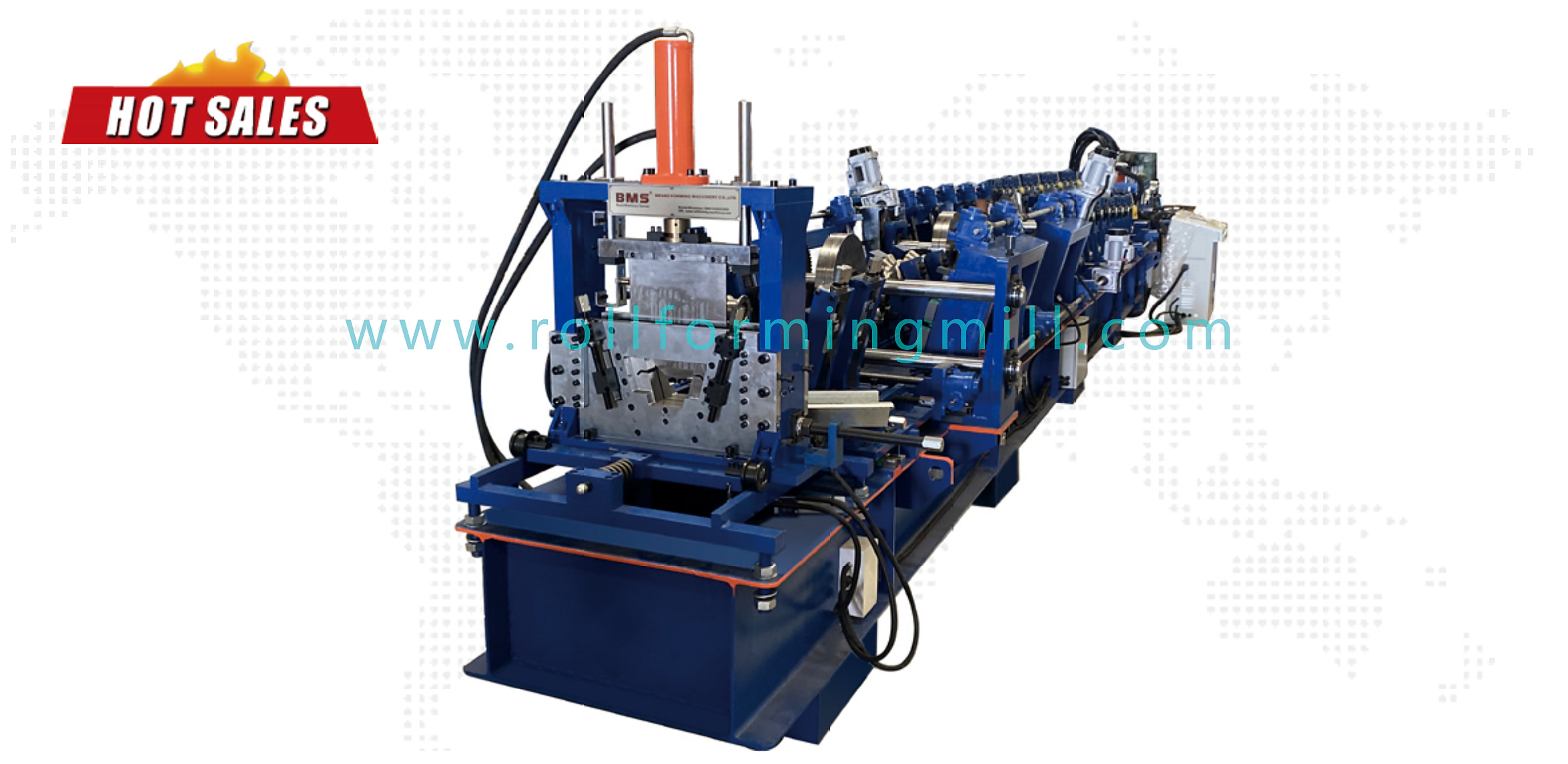
BMS hat-profile configuration
- Material
- 0.8–2.0 mm galvanized steel
- Yield strength
- ≤440 MPa
- Forming
- 16 stations · 12–18 m/min
- Motor power
- 15 kW
Forming speed is separate from accepted batch output. The complete profile/tooling agreement sets the usable combinations and remaining manual work.
Compare separate configurations
Related Omega roll forming machines
Use each model’s own drawing, material range and tooling arrangement.

Auto Changed Omega Purlin Roll Forming Machine
2.0–3.0 mm galvanized steel. Compare its defined size family and adjustment arrangement.
Explore the multi-profile Omega machine →
Roll Forming Machine for Omega
1.5–3.0 mm S320GD / S350GD. Manual transverse hole spacing; programmable longitudinal spacing.
View the machine and punching setup →Choose the production route from your order mix
Stable section
A stable section and predictable demand support an evaluation of dedicated tooling and in-house production. Compare repeat quality, the bottleneck operation and total handling effort.
Mixed-size family
Frequent width or height changes make coil-width planning, tool identification and first-article work central. Group orders only where complete geometry and material combinations allow it.
Occasional or evolving parts
Compare purchased components or subcontract work with tools, coil stock, people and plant investment. A new lip, angle or rib may need another route.
Include coil stock, slitting, tooling, lifting, utilities, operators, inspection, maintenance, trial material and outside treatment. Reusing a slitter or punch can reduce a purchase while adding transfers, buffers, revised datums or another inspection point.
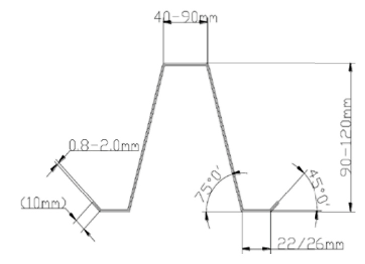
Geometry, material and tools
Approve a complete size family
Width and height adjustment applies within an agreed hat family. It does not automatically change the lips, angles, holes or tooling.
- One section
- Top face, side walls, feet or lips, inside radii, angles and stiffening features.
- One material combination
- Grade, thickness, yield, coating and developed strip width.
- One repeatable setup
- Roll, punch and cut-off tool IDs, settings and first-article requirements.
Separate minimum and maximum dimensions do not approve every combination between them.
What changes when the next SKU changes?
Width or height
Review roll positioning, entry guides, developed strip width and any size-dependent tools within the permitted family.
Holes or length
Review the program, punch access, end-distance rules, cut-off and receiving under one part ID.
A new lip, angle or rib
Review roll engagement and different punch or cut-off tools before treating the change as another size setting.
Trial common, intermediate and boundary SKUs with their own material and strip width. A successful minimum width and maximum height do not validate every crossing. Retain the drawing-to-tooling map for repeat orders, using the dimension definitions and functional datums on each approved drawing.
From coil to the finished section
Match the coil to each SKU
Use the actual material certificate and developed strip width. The same nominal thickness can produce a different forming result.
- Material properties determine springback and tool loading.
- The full section determines developed strip width.
- Coil identity connects the setup to the finished batch.
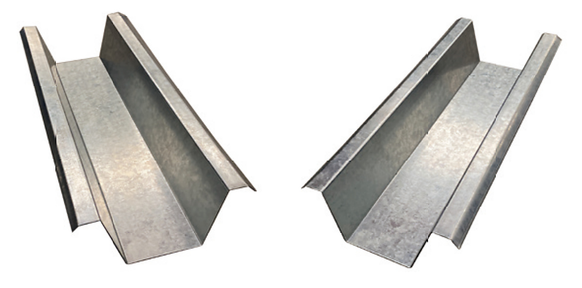
Specify strength, thickness, strip width and incoming condition
Material certificate
The hat configuration uses 0.8–2.0 mm galvanized steel with yield strength ≤440 MPa. Keep grade, yield, tensile properties, elongation/forming data and thickness basis separate. A higher-yield coil at the same thickness can change springback and tool loading.
Developed strip width
Assign width from the complete section and agreed forming process. The finished face or bottom width is not the developed width. A size change may need a new coil width as well as roll positioning.
Coil and entry condition
Record coil weight, inside/outside diameter, loading, edge burr, camber and thickness variation. Match them to entry equipment and retain coil identity with the accepted batch.
Choose the coating route and control substitutions
Pre-coated coil
Form, punch and cut in the agreed sequence. Inspect coating, exposed edges and burrs; define edge treatment against product requirements. Coating designation alone does not establish service life.
Treatment after fabrication
Include transfer, handling, outside treatment and final checks. This changes logistics, supply responsibilities and the condition in which the part is accepted.
Replacement material
Review any changed grade, yield, thickness, coating or developed width against the part/tool combination. Check the finished section, surface and assembly interfaces using the actual replacement coil; unchanged nominal thickness cannot carry every setting and approval forward.
Make holes and cut lengths one production order
Keep the hole list, cut list, quantity and drawing revision under one part ID. Check position on the formed member with the real hardware.

Define the functional datum, slot direction, transverse position, pitch, first/last-hole distances and handed variants.
Resolve near-bend holes, part ends and handed variants
Near a bend
Pre-punching flat strip offers access, but forming can move or distort a nearby feature. Processing after forming brings tool access, support, chip-clearance and cycle constraints. Choose from the actual feature and trial material; measure the finished shape and test the hardware.
At the part ends
A fixed pitch can still need a special last-hole rule. Length changes can alter first/last-hole distances, cut position and shortest-part handling.
Across variants
Identify left/right parts separately. Assign each change to its program, punch tools, location method, cut-off tools, receiving arrangement or second operation. Correct hole diameter alone does not establish joint fit.
Measure changeover to the first approved part
Count from the last accepted part of A to approval of the first part of B, including coil, tools, trial material and inspection.
- StartLast accepted A
- PrepareCoil, tools & program
- ChangePosition & exchange
- VerifyTrial & inspect
- FinishFirst approved B
Automatic positioning is one part of the change. Coil width, guides, punch tools, cut-off tools and release work can still change.
A → B → A checks recovery. The returned part must meet section, hole, length and free-state requirements.
Assign the full changeover work and timing
Distinguish a length-only change from size, material, hole-pattern or section-family changes. Assign recipe selection, roll positioning, coil width, guides, punch tools, cut-off tools and first-article release to each transition.
Bottom-width and wall-height adjustment does not move every guide or exchange every tool. Matching the screen setting is only one step in recovering the original SKU.
Record movement time and complete changeover separately. Identify offline preparation, concurrent tasks and trial consumption without double-counting overlaps. Mixed orders can add coil handling and first-article work even when positioning is fast; use the representative order sequence.
Connect the equipment to your production flow
Define the stations, process sequence and plant interfaces. The quoted scope must cover the work between incoming coil and accepted parts.
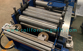
Feeding
Match strip width, coil condition and entry settings to the SKU.
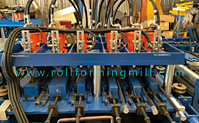
Punching
Assign the hole tools, locating method and agreed process position.
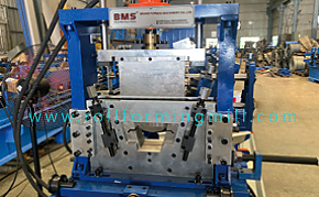
Post cutting
Match the cut-off tool and receiving support to the finished section.
Coil preparation / slitting → Decoiling & entry → Hole processing & forming → Post cutting → Receiving & packing
Review the hat-profile equipment
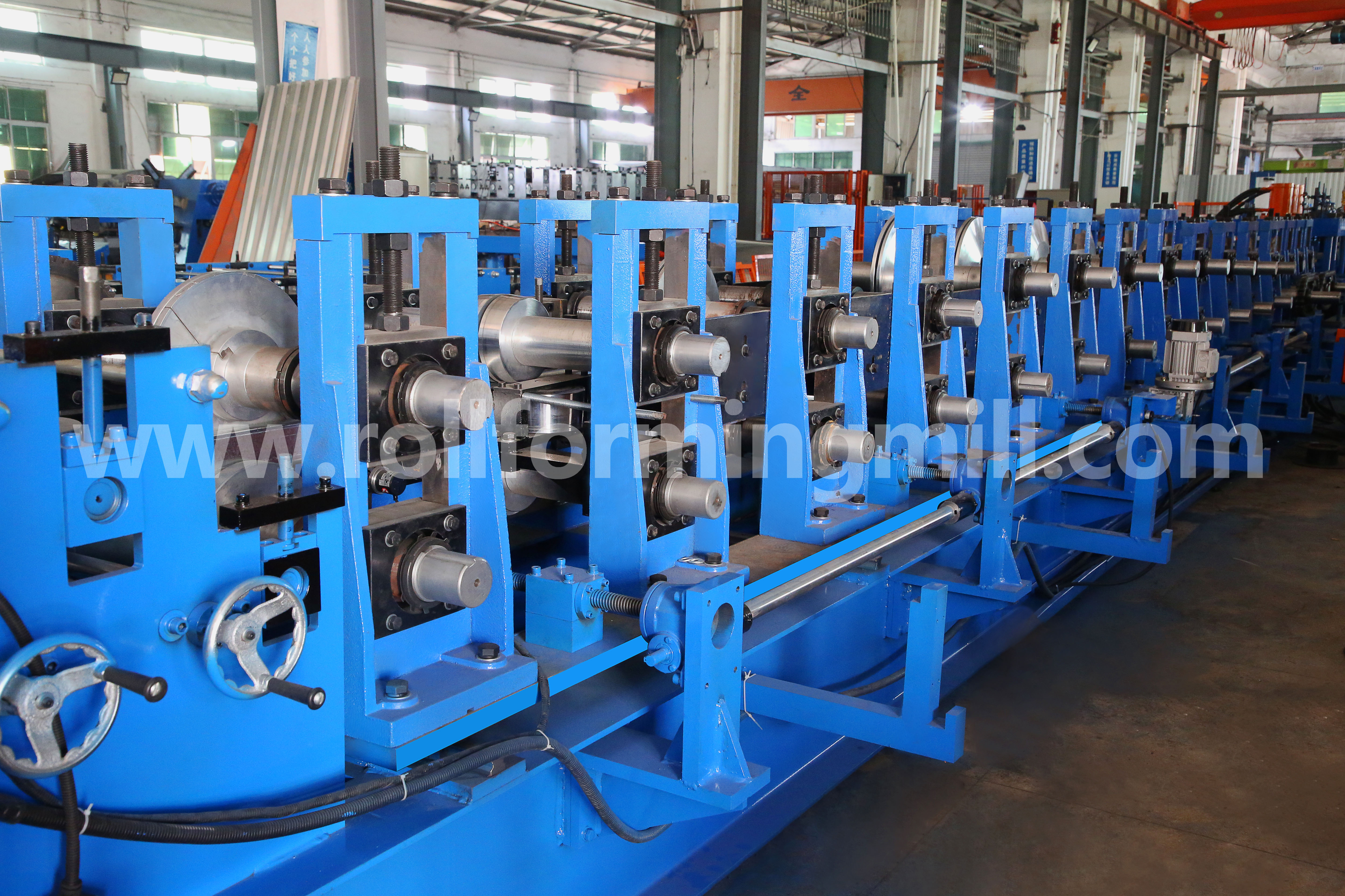
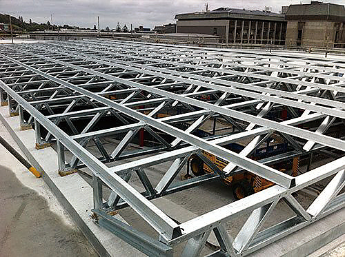
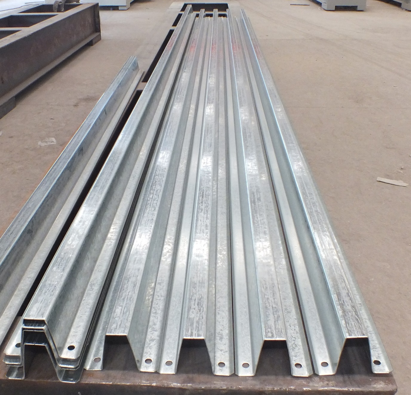
Component photographs, section drawing and configuration figures.
Define equipment ownership and plant interfaces
Process and site
The agreed layout sets the punching position, part support, operation timing and interfaces. Add outside treatment where the product requires it. Existing punching or slitting may reduce the purchase while requiring transfers, buffers, revised datums and inspection; define who adapts and tests the combined process.
Allow for coil storage/lifting, threading, operation and maintenance, longest-part support, inspection, packing and traffic. Include floor/site conditions, utility connections and the complete line load schedule.
Supply ownership
Included: quoted stations, tools, controls and acceptance items. Optional: extra receiving or handling, with interfaces and maintenance needs. Buyer prepared: existing equipment, utilities, lifting, inspection and responsible parties. Outside work: transport, treatment, finishing and final acceptance.
Configuration and planning
The hat configuration lists 15 kW motor power, 12–18 m/min forming speed and a Cr12 cut-off blade. Size plant power from the full line load; evaluate accepted output with actual hole/length orders. Blade material is separate from roll material. Specify the included stations and agreed processing sequence in the quotation.
Compare accepted output
Use accepted pieces or accepted length over an agreed production window, with the included stops and changes stated.
Agreed occupied hours
Or sum accepted lengths over the same hours.
Which order exposes your bottleneck?
Feed, cut-off and longest-part support
Longer parts with fewer holes expose handling and receiving limits. Record lengths, hole pattern, accepted quantity and the time spent on the whole order.
Repeated operations per part
Dense holes and short lengths increase punch/cut cycles and unloading frequency. Faster forming may leave the same bottleneck. Trial the real hole list and shortest-part handling.
Preparation, changeover and release
Small batches with size or material changes can spend more time preparing, trialling and releasing parts. Include complete changes for the representative sequence.
Include the agreed stops and changes. Separate steady running from complete-order output.
Keep material consumption and time on the same basis
State whether coil changes, size changes, first articles and receiving are inside the production window. Forming speed × shift hours omits this work. Separate planned punch/cut/head-and-tail loss, setup/changeover consumption and rejected parts. Fix the consumed material, accepted product, remaining coil and opening/closing work-in-progress basis before calculating a ratio. Purchased coil weight is not automatically one batch’s consumption.
Record event start/finish and concurrent work without double-counting. Keep kilograms, metres and pieces on their stated basis.
From cut-off to dispatch
Protect the finished member
Judge the cut, unrestrained part. Preserve its geometry, surface and identity through receiving and packing.
- SupportReceive at the required cycle without losing shape.
- SeparateKeep lengths, holes and handed variants identifiable.
- ProtectCheck bundle supports, contact points and surfaces.
- ReleaseMatch quantity and labels to the accepted batch.
Check free-state geometry, surfaces and batch identity
A member held straight in the line may change when cut. Define support and measurement conditions for end shape, straightness and twist against separate drawing characteristics.
Compare incoming strip, roll contact, cut-off, receiving and packed condition. Give coating damage, exposed edges and burrs their own acceptance criteria.
The same section can carry different holes, materials, handedness or revisions. Retain the part ID through sorting, counts, labels and dispatch. Slow or inadequate receiving can damage a part or restrict output; assign manual/automatic handling, packing equipment and check points in the supply scope.
Release a part that fits the assembly
Check the first article against separate drawing characteristics and actual mating hardware. Continue with a defined batch inspection plan.
- SectionGeometry, angles, radii and functional datums.
- HolesFinished shape, position and first/last-hole distances.
- Cut partLength, ends, free-state straightness, twist, burrs and surface.
- AssemblyReal hardware, contact faces and fastener access.
Set release rules and respond to a failed check
Record tolerances, measuring method, support condition, results and release responsibility. Correct hole size can still fail a joint when its formed position, end distance or orientation is wrong.
Define which size, hole, tool, material and restart events require a new first article. One accepted part does not establish stability for the remaining batch.
If a check fails, isolate affected production, retain its coil and setup identity, correct the cause and verify recovery before release.
- Hole or end-distance mismatch: retain feature, datum and program information; examine relevant punching, feeding and cut-off stages, then verify the correction.
- Bend or twist: distinguish in-line restraint from free-state behaviour; preserve material, settings and support conditions.
- Surface marks: compare incoming material, contact points, receiving and packing; locate where the condition changes before assigning a cause.
Agree how the machine will be accepted
Use representative profile/material combinations, repeated changeovers and real batch work. Define the production checks to repeat at your site.
Factory acceptance
Check common, intermediate and risky boundary SKUs, hardware fit, A → B → A recovery and accepted batch output.
Site acceptance
Verify installation and utilities, then repeat the agreed production and assembly checks with the site’s coil and handling.
Inspect before delivery
BMS provides a pre-shipment inspection path for your engineers or an appointed third party.
Factory inspection and commissioning information →Choose the trial parts, witnesses and failure-closure rules
Contract the real materials, lengths and holes for common, intermediate and risky boundary SKUs. Combine conditions only where the profile family permits them: the easiest middle-sized part cannot replace the contracted risks, and unrelated extreme values do not define a valid test part.
Record separate dimensional results, hardware fit, repeated changeovers and batch work. Include receiving, part identity and the quoted equipment/tooling scope. Assign trial coil, tools, hardware, gauges, lifting, measuring methods, criteria and witnesses in advance.
At the site, verify installation, connections and utilities under the agreed commissioning procedure. Use actual site coil, interfaces and handling for the specified production checks; recheck relevant part and assembly results after transport and installation.
Record actual results, witnesses, exceptions and approval. Assign failed conditions, affected parts and corrections to an owner, then define recheck and closure before transferring files, tools and responsibilities. Video supports observation; dimensions and trial fit need their own records.
From member to mounting system
Keep the engineering handoff clear
Manufacturing acceptance establishes part conformity. System loads, joints, durability and project approval need their own engineering evaluation.
- Transfer the controlled part and material records.
- Evaluate the specified member-and-connection combination.
- Apply the actual project and site conditions.
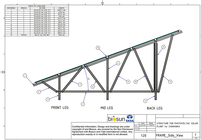
Transfer manufacturing records into the system evaluation
Manufacturing
Transfer the controlled part/assembly revision, material identity, measured results, hardware fit and any deviations or changes. State which manufacturing requirements are met.
System engineering
Evaluate the specified modules, members, fasteners, connections, loads, durability and electrical/bonding requirements where applicable.
Project team
Apply actual site conditions and applicable approval requirements. Manufacturing records are inputs to this evaluation. Changes to thickness, yield, section, holes or joints can affect manufacturability and the system evaluation; route them to the responsible engineer before reusing an earlier approval.
For a US project using UL 2703 evaluation, check the actual Listing and installation conditions for the specified combination. See UL Product iQ certification information.
Prepare the people, plant and handover
Plan site readiness, task-based training, identifiable tooling and support terms before production starts.
Ready plant
Prepared power, trial material, hydraulic oil, lifting and assisting staff.
Controlled files & tools
Permitted SKU revisions, setup backups and identifiable rolls, punches, dies and blades.
Trained operators
Permitted orders, complete changes, first articles and demonstrated stop/restart recovery.
Define commissioning, training, spares and ongoing support
BMS’s commissioning and technician-training arrangements depend on the prepared site. Define the visit, installation and training scope in the order.
Training should cover production, size/hole changes, first-article cooperation, abnormal stop/restart and recording, plus tool care, controlled backup and demonstrated recovery.
Hand over permitted SKU/drawing versions, materials/strip widths, settings, inspection requirements and controlled backups. Identify roll, punch/die and blade IDs, maintenance points and matching replacement information. Select spares by use, downtime impact and supply conditions.
Record training tasks, service contacts and responsibilities. Separate remote diagnosis, site visit, response and repair. Agree location, period, labour, travel, parts, exclusions and responsibilities, including the warranty start and conditions for the quoted configuration.
Include drawing units, working language and plant conditions in the RFQ. Service terms and support options →
Practical buying questions
Before you choose a machine
Connect the part, tooling and production scope.
Prepare your production brief →The hat-profile task is a defined family of steel parts. Other sections, accessories and processes have their own tooling and supply scopes. Start from the component and assembly drawings, then use the relevant product route for another section. Compare the production routes.
It can. Developed strip width belongs to the complete section and material combination for each SKU. Roll positioning does not establish that all sizes use one coil width. Plan the approved strip widths and the associated coil changes. Review the coil inputs.
Bottom-width and height size adjustment is one task. Punch tools, transverse/longitudinal hole settings, guides and cut-off tooling have their own arrangement. Map the actual actions for a length, size, material, hole or section change. See the complete changeover method.
Start at the old order’s last accepted part and end when the new first article is approved. Record mechanism travel, offline preparation, concurrent work and trial consumption separately. Also test recovery through A → B → A. Follow the timing sequence.
Evaluate its shape and functional position after forming and test the actual mating hardware. Pre-punch access must be weighed against forming distortion; processing after forming has access, support and cycle constraints. Plan the hole and length together.
The specified yield strength for this hat configuration is no higher than 440 MPa. A substitute grade, thickness or coating needs review with its material documents, geometry and tooling, followed by the relevant finished-part checks. Compare material conditions.
Use the actual hole list, cut length, quantity and receiving arrangement. Count accepted parts or accepted length over the agreed occupied time, with the included stops and changes stated. Choose a representative order mix.
A drawing, sketch or sample photos, the material and thickness you know, and the hole/length requirement or current production problem are useful starting inputs. Complete the controlled technical RFQ as the configuration develops. Prepare the first discussion.
The quotation and its attachments should identify included equipment, options, buyer-prepared items and outside work. Receiving, packing and site work each have their own interfaces and acceptance responsibilities. Define the supply scope.
Compare the applicable start date, period, location, labour, travel, parts, exclusions and responsibilities for the quoted configuration. Keep remote diagnosis and site support distinct, and define what happens after an issue is reported. Plan commissioning and support.
From your part to a production proposal
Plan your hat profile production with BMS
Start with the information you have. Align the profile family, tooling and process scope, then develop the detailed technical RFQ.
Review the Hat Profile Brochure (PDF)
Your part
A section drawing, sketch or sample photos, plus the size changes you need.
Your material
Known grade, thickness and coating or finished-surface requirement.
Your orders
Holes, cut lengths and batch size, or the current production problem.
Prepare a detailed technical RFQ
- Part and assembly drawings, revision, part IDs and mating hardware.
- Complete size family, frequent transitions and any new lips, angles or ribs.
- Material certificate, thickness, yield, coating, developed strip width and coil dimensions for each SKU.
- Hole and cut lists, handed parts, quantities, order sequence and required dates.
- Existing processes, current bottleneck and accepted-output target with its time basis.
- Characteristic tolerances, surface and assembly requirements, and factory/site acceptance criteria.
- Plant layout, power and other utilities, loading, receiving and inspection arrangements.
- Responsibilities for system engineering, outside processes, training and ongoing support.