


BMS · IN-PLANT ROOF PANEL PRODUCTION
INDUSTRIAL ROOFING AND COMMERCIAL ROOFING ROLL FORMING MACHINES
Roof panel production built around your profile, coil and cut list.
Plan a fixed-workshop line around the roof panel you sell: its profile, actual coil and order lengths. Compare standing-seam, concealed-fix and industrial trapezoidal panel routes, then match forming, profile shearing and receiving to your cut list.
Start with Your Roof Panel Profile
Industrial roof-panel orders may call for trapezoidal or corrugated sheets, mechanically seamed panels, or concealed-fix profiles. Start with the panel drawing and connection method; each family needs its own forming and cutting configuration.
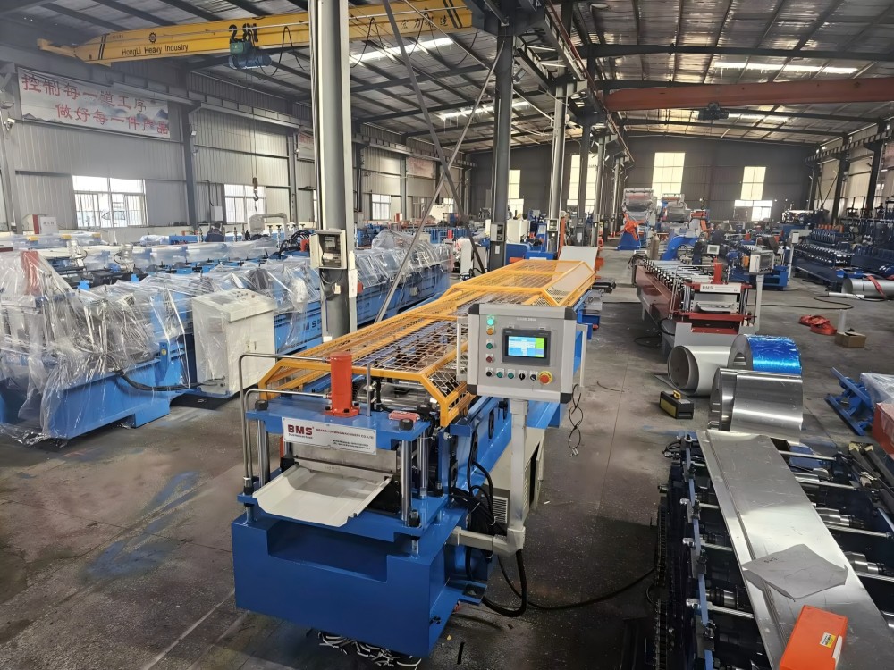
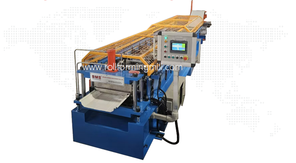
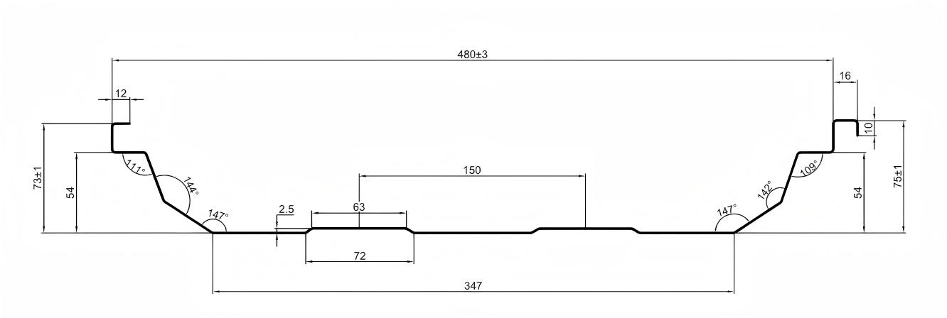
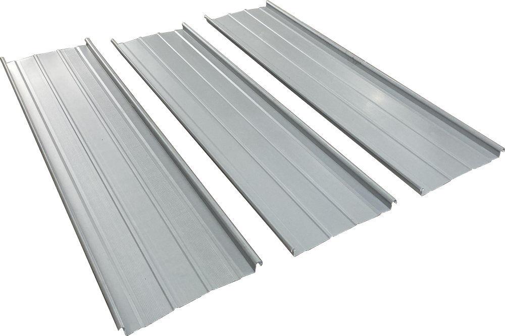
A standing seam roll forming machine must match the panel’s ribs, mating edges and finished dimensions. The machine and section illustrations below show this profile family.
Three Widths, Three Measurements
Use one dimensioned drawing to locate the ribs, mating edges and panel face, with tolerances at the required measuring points.
Feed width
Flat strip entering the machine. Allow for the material taken up by ribs and connecting edges; feed width is not roof coverage.
Finished overall width
Outside edge to outside edge of one formed panel, including its connecting geometry. Use the drawing’s specified measuring points.
Cover width
Repeating installed width between equivalent points on neighboring panels after the specified connection is made.
Changing cut length keeps the same section. A different rib, edge or panel width needs its own tooling and mating-part review.
Changing Length or Changing the Section?
- Length or quantity changes
- Keep the approved section and material. Revisit cut frequency, length control, receiving and pack quantities.
- Rib, edge or panel width changes
- Review roll tooling, guides, cutter shape and mating parts. A cut-length setting cannot create another cross-section.
- Holes or notches change
- Define feature shape and its position datum along the panel. This changes the operation, tools and control requirements.
- Material or coating changes
- Reassess forming, cutting and surface requirements with the actual coil data and a representative sample.
Include thickness, grade, yield and tensile data, coating and feed width at the first review. A matching profile with different coil conditions can require a different forming or cutting assessment.
Profile Systems We Form
BMS supplies tooling for Al-Mg-Mn aluminum and steel profiles in the following styles. Match the section, clip interface and closing method to the project drawing.
- Kalzip
- Lysaght
- BEMO
- Kingspan
- Cherng Ji
- LCP
- NTM SSH Multipro
- Zamil
A style reference identifies the profile to develop; the selected roof assembly still needs its own connection and performance evidence.
Plan the Panel Connection
The formed edges, neighboring panel, clips and closing method must fit together. A seam name alone is not a compatibility check.
Match the Complete Connection
Review both panel edges with the specified clip, fastener and support detail. Keep the drawings and mating parts at the same revision; one loose panel does not show the complete joint.
Identify How the Joint Closes
Snap connections and mechanically closed seams use different geometry and installation processes. Where mechanical closing is required, match the tool and method to that system and check a representative joined sample.
Keep Forming and Installation Separate
The roll former makes the panel; installation equipment joins or closes it under the roof-system instructions. Wind and water performance is assessed for the complete roof assembly.
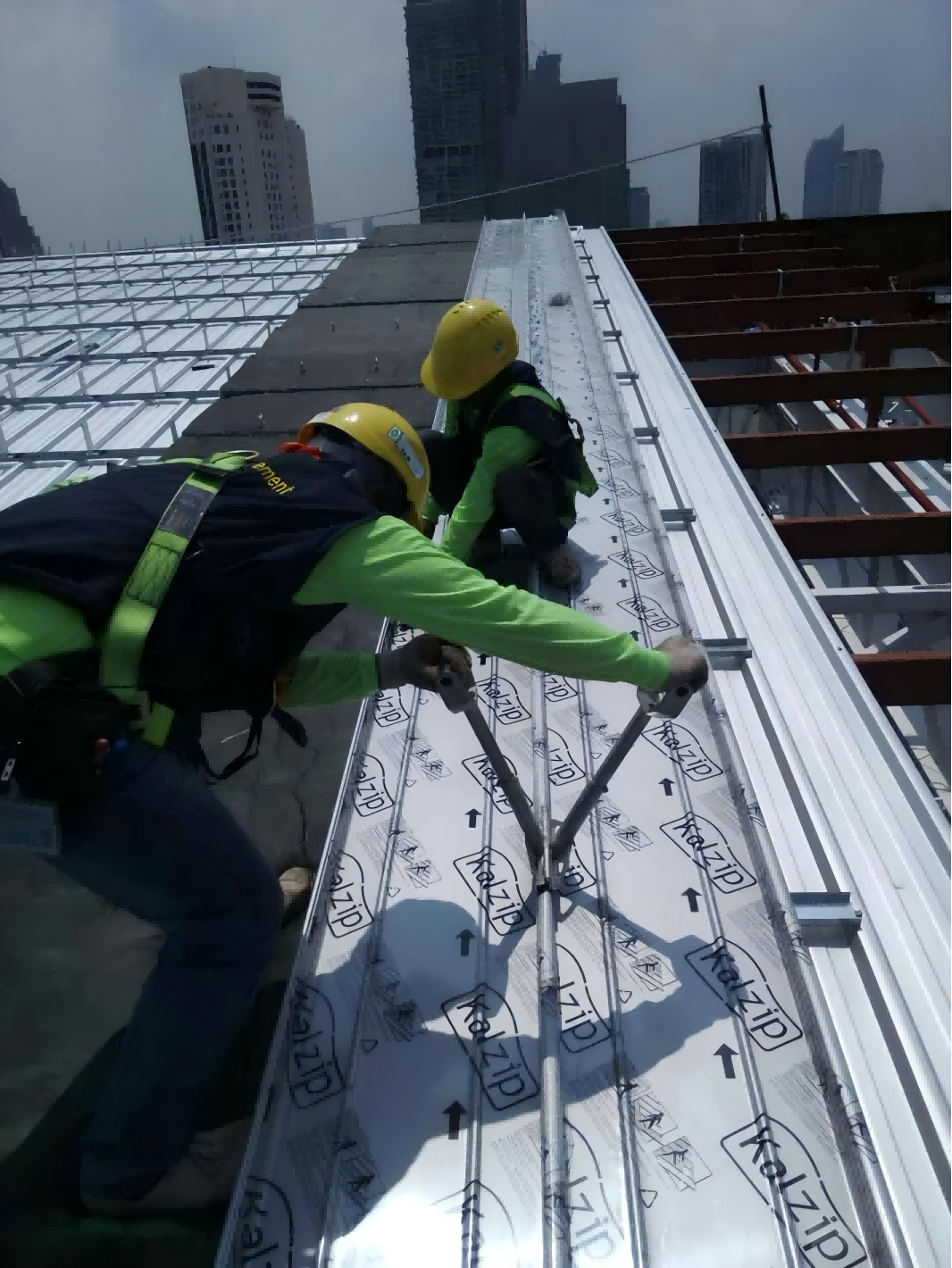
Use the seam detail, material and specified closing process to select installation equipment.
BMS roof-seamer selection guide430 Roof Seamers: Two-Roll or Three-Roll
BMS supplies two-roll and three-roll 430 seamers. Both use 220 V single-phase power, a 2.2 kW motor, a stated closing-thickness range of 0.6–1.6 mm and a closing speed of 16–22 m/min.
Three-Roll 430 Seamer
370 × 330 × 550 mm · 26 kg.
Two-Roll 430 Seamer
210 × 280 × 380 mm · 15 kg.
Match the tool’s rollers and closing sequence to the specified seam, alloy, coating and material thickness. These are installation-tool specifications, separate from the roll former’s forming speed.
Choose Your Production Route
Factory supply works when the workshop can form, receive and dispatch the actual order. Long-panel logistics or infrequent demand can make another route more practical.
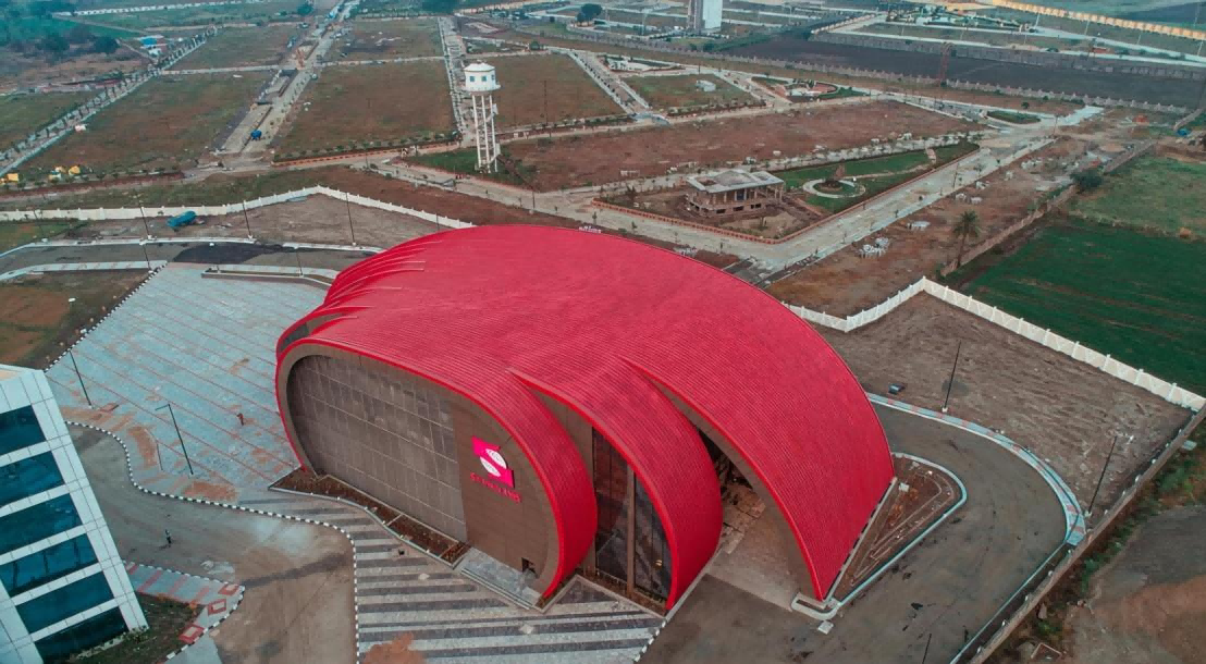
Compare the Same Order
In-plant production Recurring target sections, workshop resources and control of production scheduling.
Coil inventory, receiving, packing and transport must support the ordered lengths.
Compare your length distribution and demand frequency with a layout that follows the panels from the workshop to loading.
Purchased panels Low-frequency work or orders that do not justify dedicated forming and handling resources.
Check the supplier’s profile and material scope, lead time, delivery limits and the risk of damage during handling.
Obtain a delivered-panel quotation for the same section, coil, quantities and delivery dates.
Rental or site forming Site production can reduce long-panel transport constraints when the equipment and location are suitable.
Assess machine availability, site access, utilities, crew, receiving space and weather conditions.
Base the comparison on an identified machine configuration and the site’s actual working conditions.
Balance Demand with Dispatch
A factory standing seam roll former suits repeat profile work when coil stock, labor, scheduling and dispatch resources support the order. Long panels still need suitable space, protection and transport.
Purchased panels and equipment suited to site forming can complement in-plant production. Compare costs and logistics for the actual order mix; there is no universal volume or payback threshold.
A BMS Configuration for Site Production
BMS can configure standing-seam lines in 20 ft or 40 ft containers as mobile roll-forming factories. For very long roof runs or complex geometry, production near the installation area can reduce finished-panel transport and repeated handling.
Compare the container layout, access, power supply, crew and receiving route with the factory option. Coordinate production with installation; the workshop machine illustrated on this page is a separate configuration.
Explore BMS container-based roof-panel productionContainer-based configurations
Turn Your Cut List into a Production Plan
Specify a standing seam panel machine against the cut list: panel and material revision, finished lengths, quantities and any positioned features. Equal total meters can mean very different cutting and handling work.
01
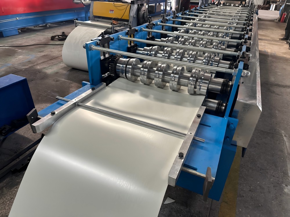
Feeding
Guide the specified strip into the line. Match feed width, entry guides and coil pay-off to the material and panel drawing.
02
Feature Requirements
If the order needs holes or notches, specify their shape, spacing and end or feature datum. The selected tooling, operation location and controls must support those requirements.
03
Forming and Profile Shearing
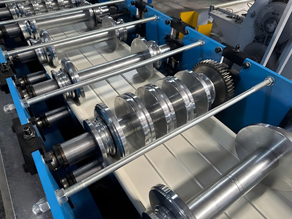
The rolls create the section; a hydraulic profile shear (post-cut) cuts it to length. Its blade geometry follows the formed profile to support the standing edges during cutting, helping prevent their collapse. Check the cut on the selected coil and identify which operations stop the line.
Watch a BMS YX65-430 Line in Operation
Follow the strip through the feeding guides, forming rollers and outlet cutting area. This YX65-430 configuration shows how the panel takes shape along the line.
The machine shown forms the YX65-430 profile. Compare its process arrangement with the geometry and operations required for your panel.
Keep Each Order Line Traceable
Drawing revision · coil reference · finished length · quantity · feature drawing and datum · batch or pack mark.
Separate different lengths or features into their own lines. Many short pieces add cut and handling events; long panels can make receiving, inspection or packing the limiting operation.
Plan the Work, Then Check the Panel
Each change affects tooling, scheduling or handling. Set the matching inspection requirement before production.
Profile and material revision
Match the rolls, guides and cutter to the drawing revision and coil conditions.
Verify the resulting section’s identity, critical dimensions and surface finish.
Lengths, quantities and batch sequence
Set the cutting frequency and batch sequence, with receiving arrangements and pack marks for each order line.
Reconcile accepted panel lengths and quantities with that same cut list.
Holes/notches and position datums
Specify the feature tooling, operation order, controls and position relative to the cut ends.
Measure the hole or notch shape and location from the same specified datum.
Curvature or changing width
Define the final lengthwise shape and any width variation so the process assessment includes suitable infeed and outfeed interfaces.
Evaluate the resulting geometry and connection fit on a representative sample.
Build the Process for Curved and Tapered Panels
BMS supplies automatic size-changing curving equipment with taper capability and automatic tapered-sheet slitting equipment. Curving changes the lengthwise shape; tapering changes the developed width. A cut-length setting cannot create either geometry.
YX65-230/600 Curving Machine
230–600 mm adjustable processing range; 0.8–1.2 mm aluminum; 18 m/min; 2.2 kW.
Automatic Tapered-Sheet Slitter
Up to 1,300 mm processing width; Al-Mg-Mn 0.76–1.2 mm or color steel 0.3–0.7 mm; 18 m/min.
Match the Curving and Taper Operations
The YX65-230/600 curving machine uses heat-treated Cr15 rollers with hard-chrome plating. The tapered-sheet slitter has a stated width change of up to 150 mm over 1 m.
Define the finished curvature or taper, strip-development drawing, seam requirements and joined-sample checks. Coordinate slitting, forming, curving and receiving interfaces around that geometry; the selected equipment package determines the process sequence.
Match Coil to Your Panel Profile
BMS YX65 configurations form color steel and Al-Mg-Mn aluminum. Select the material, thickness, yield grade and section together, then assess representative coil samples against the required geometry and finish.

How Coil Properties Affect the Line
- Grade, thickness and strength
- Grade and strength affect forming and springback. Compare yield and tensile data separately with the target section, thickness and trial coil.
- Coating, surface and feed width
- Specify the metallic or paint coating, finish criteria and flat feed width. They affect guides, tooling contact, cut edges and sample inspection.
- Coil loading and pay-off
- Size the auxiliary equipment and its interfaces around:
- Coil mass and inside/outside diameters
- Loading method and pay-off requirements
When Coil Needs Slitting
For coil wider than the required feed strip, plan a separate slitting supply or preparation process. Match the slit width to the panel drawing before forming.
When the Material Changes
Al-Mg-Mn aluminum is part of the YX65 material scope shown below. A different alloy or temper, copper, higher-strength steel or a thickness outside the selected configuration needs a material and tooling review. Similar thickness alone does not establish suitability.
| Parameter | YX65-430 | YX65-300/400/500/600 | YX65-418 |
|---|---|---|---|
| Applicable material | Color steel (GI/PPGI/PPGL); Al-Mg-Mn aluminum | Color steel (GI/PPGI/PPGL); Al-Mg-Mn aluminum | Color steel (GI/PPGI/PPGL); Al-Mg-Mn aluminum |
| Color-steel thickness | 0.4–0.80 mm | 0.4–0.80 mm | 0.4–0.80 mm |
| Al-Mg-Mn thickness | 0.8–1.2 mm | 0.8–1.2 mm | 0.8–1.2 mm |
| Yield strength / grade | Steel: G300 or G550; aluminum: selected alloy and temper | Steel: G300 or G550; aluminum: selected alloy and temper | Steel: G300 or G550; aluminum: selected alloy and temper |
| Cover width | 430 mm | 300 / 400 / 500 / 600 mm | 418 mm |
| Feed width | Developed strip width for the selected profile drawing | Developed strip width for the selected profile drawing | Developed strip width for the selected profile drawing |
| Forming stations | 14 or 17, by configuration | 14 or 17, by configuration | 14 or 17, by configuration |
| Forming speed | 20–25 m/min | 20–25 m/min | 18–20 m/min |
| Main motor | 7.5 kW, VFD | 7.5 kW, VFD | 7.5 kW, VFD |
| Cutting | Hydraulic profile shear; Cr12MoV, heat treated | Hydraulic profile shear; Cr12MoV, heat treated | Hydraulic profile shear; Cr12MoV, heat treated |
| Body frame | H400 or H450, by configuration | H400 or H450, by configuration | H400 or H450, by configuration |
| Matched equipment | Curving machine with taper capability; tapered-sheet slitter; suitable roof seamer | Curving machine with taper capability; tapered-sheet slitter; suitable roof seamer | Curving machine with taper capability; tapered-sheet slitter; suitable roof seamer |
Scroll the comparison horizontally on smaller screens. Cover widths are profile choices, not feed-strip widths or a promise that one tooling set makes every section. Select the 14- or 17-station layout, frame and matched equipment as a configuration. The 7.5 kW motor rating is separate from total-line electrical demand.
Measure Output on the Orders You Run
Use accepted output over the agreed batch time to assess production. YX65-430 and YX65-300/400/500/600 configurations have a forming-speed specification of 20–25 m/min; YX65-418 is 18–20 m/min. This describes forming movement, not accepted panels per hour.
Set the Start and Finish
Identify the drawing, coil, configuration, cut list and batch size. Agree whether timing begins with coil/set-up work or with the first production panel, and whether it ends at cutting, inspection or packed handover.
Use the same boundary for every comparison. Record forming time separately from elapsed batch time.
Record Stops and Overlapping Work
Log cutting/punching stops, coil changes, settings, faults and waiting for receiving or packing. Record actual event start and end times; some inspection and handling may overlap production.
Keep one elapsed-time record for the batch. Summing overlapping tasks would count the same minutes twice.
Count Only Accepted Output
Separate trial pieces and rejected pieces from accepted panels. For mixed lengths, total the accepted quantity × finished length for each order line.
Divide accepted meters by elapsed hours, or accepted piece count by the same elapsed hours for pieces/hour. Keep the rejection and stoppage records with the result.
Compare mixed-length orders under the same timing boundary: frequent short cuts and long-panel receiving can change output at the same forming speed. Define the acceptance run
Keep Long Panels Moving Through Your Workshop
Plan the longest finished panel through the entire workshop-to-delivery route. The machine footprint is only one part of that space requirement.

Support the Panel Beyond the Cutter
- Check the complete route
Map the line exit, support and inspection area, transfer points, temporary storage, packing and loading. Check doors and turns.
- Size the receiving arrangement
Match supports, staffing and handling equipment to panel length, mass, stiffness and finish. Set the maximum panel length the arrangement can receive.
- Plan packing and dispatch
Define bundle protection, loading and receipt at the destination. Include any required forklift or automatic stacker in the supply scope.
When Space Changes the Route
- The longest panel cannot clear the exit
- Change receiving space or orientation, or reassess the manufacturing route before ordering the layout.
- Inspection or packing holds up the line
- Review support, transfer resources and batch/pack flow together with the output trial.
- The pack cannot reach the vehicle or destination
- Revisit doors, turning points, loading method, transport and destination handover conditions.
If transport limits the panel length you can deliver, compare factory supply with equipment suited to site forming. See the production-location comparison.
Check Finished Panel Quality
Accept panels against defined dimensions, finish and connection criteria using the actual coil and a representative order. Agree the sampling and measuring conditions before the trial.
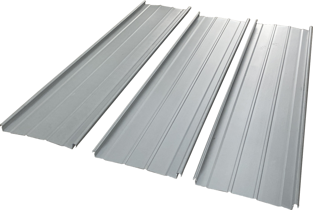
Keep the Sample with Its Production Record
Link every sample to its drawing revision, coil specification, machine configuration and order line. Record dimensions and feature positions as measurements; use photographs to document visible appearance.
Define the Panel Checks
Section geometry
Measure the section against the agreed drawing revision and its datums, measurement points and tolerances. Specify instruments and sampling before the run.
Retain the identified sample and section measurements. The drawing owner, line supplier and QC reviewer should agree the inspection method.
Length and positioned features
Check panel length and hole or notch positions from the cut list’s end and feature datums, using the configured tools and agreed measuring method.
Record accepted lengths, quantities and feature positions by order line. Production and QC need the same datum references.
Cut end and surface
Inspect cut ends and surfaces on representative lengths made from the actual coil. Compare the coil and formed panel against the agreed edge and finish criteria.
Retain those comparisons and observations. The buyer defines the required finish; the acceptance plan identifies who reviews it.
Straightness and handling
Assess straightness at the agreed production stage, stating how the panel is supported and observed. Retain a representative panel and its handling history.
Production, handling and QC should identify the stage under review so forming and handling effects can be investigated separately.
Connection fit
Assemble a sample with the specified neighboring panel, mating parts and closing method. The system or interface owner defines the fit and closing criteria.
Identify and retain the joined sample with the parts and method used. Its result applies to that interface.
When a Sample Does Not Match
- An edge or joint does not fit
- Compare the same drawing/system revision, actual panel measurements, tooling, coil and specified mating parts.
- Length, holes or cut ends differ
- Compare order datums, configured controls and operations, tools, support and measured samples.
- A long panel looks different
- Compare incoming coil, formed panels, representative length, receiving/transfer and observation conditions.
- Visible waviness / oil canning
- Review material, design, forming, handling and installation factors at the relevant stage. Do not assign one cause from a photograph.
Use the machine instructions and matched production records to investigate an adjustment.
Discuss the Acceptance ScopeWhat BMS Measures
BMS’s in-house inspection resources include roller-hardness testing, shaft radial-runout measurement, CMM inspection and a three-in-one gauge for finished-section checks.
- Profile geometry: a ±0.5 mm profile-gauge checking criterion, applied to the specified section and measurement points.
- Traceable measurement: calibrated measuring instruments and inspection reports available on request.
- Order acceptance: connect those measurements to the drawing, actual coil and representative trial. The gauge criterion does not define every dimension or the complete roof’s performance.
Panel, Joint and Roof Performance
Manufactured-panel acceptance, connection fit and roof-system performance answer different questions. Carry each record to the party responsible for the next decision.
What Was Produced?
Keep the drawing, actual coil, configuration, cut list, sample identity and measurements. The buyer’s production/QC reviewer and line supplier use these for equipment acceptance.
What Was Joined?
Identify adjacent panels, clips and other mating parts, closing tools and system instructions. The specified system/interface owner defines the fit and installation requirements.
What Assembly Is Assessed?
Wind, water, slope and span requirements need evidence for the specified assembly and project, provided through the roof-system supplier or project engineer. Machine parameters and machinery certificates cannot replace that evidence.
For the United States, Saudi Arabia, Russia, India or Mexico, state the destination and project document requirements in the brief. Assess the selected configuration, system evidence and support terms for that destination.
Compare BMS Roof-Panel Lines
BMS roof-panel machines serve different profile families. Compare the section drawing, coil conditions and required operations before selecting a configuration.
Industrial Roof Panel Machine: Trapezoidal or Corrugated
This production route is for industrial profiled sheets, separate from the YX65 standing-seam configurations. Select the rib pattern, overlap and fastening detail from the panel drawing.
The 1,000 mm-cover reference configuration uses a 1,219 mm feed strip. These are different dimensions: forming the ribs and connecting edges uses part of the flat strip width.
Explore BMS industrial roof-panel machines1,000 mm-Cover Configuration
- Material
- Galvanized or color-coated steel; 0.3–0.8 mm
- Material strength
- 235–390 MPa; specify the coil’s yield and tensile basis
- Feed / cover width
- 1,219 mm / 1,000 mm
- Forming speed
- Approximately 15–18 m/min
- Machine envelope
- Approximately 9.5 × 1.8 × 1.6 m; approximately 8 tonnes
The machine envelope excludes the complete coil-loading, receiving and handling layout. Use the selected profile’s supply scope for the production plan.
Standing-Seam and Concealed-Fix Configurations
Mechanically seamed: YX65-300/400/430/500/600, YX65-418 and YX25-220/430/550 families.
Concealed-fix / snap-lock: Klip-Lok-style profiles and snap-lock configurations such as the 465 mm-cover line. Match their clip engagement and closing process to the specific drawing.

Mechanically seamed
YX65-300/400/430/500/600 Standing-Seam Line
The YX65 family includes 300, 400, 430, 500 and 600 mm-cover profiles. Select the section, width configuration and matched operations for the actual order.
View this configuration
Concealed-fix
Klip-Lok-Style Line — 700 mm Cover
Lysaght-compatible profile geometry is assessed against the selected section and clip drawing. The 700 mm cover width is separate from the feed-strip requirement.
View this configuration
Concealed-fix / snap-lock
Concealed-Fix (Snap-Lock) Line — 465 mm Cover
The YX77-465 configuration forms a 465 mm-cover snap-lock profile. Match its mating edges, clip interface and coil grade to the required assembly.
View this configuration
Concealed-fix / snap-lock
Snap-Lock Roof Panel Line
Use the exact snap-lock edge geometry, clip detail and coil specification to establish the required line and connection fit.
View this configurationScroll to compare all four configurations.
Roof-Panel Machine Layout and Details
View the illustrated machine, section drawing, feeding arrangement and profile shear. Use the model comparison above to define the selected line configuration.
Define What the Quotation Includes
For comparable quotations, use the same profile, coil, order functions, drawing revision and destination. Mark each item as included, optional, buyer-supplied or excluded, and name the owner of each equipment interface.
- Main line and profile tooling
- Identify drawing revision, rolls, guides, controls and the specified punching/profile-shearing functions.
- Coil and finished-panel handling
- List decoiling/loading, any separate strip preparation, receiving, transfer, packing and further operations.
- Documents, spares and services
- Name technical, electrical and operating files; acceptance records; document language; wear parts; commissioning, training and support charges.
Budget labor, material losses, consumables, inventory, logistics and services alongside the line. Profit and payback calculations need project costs and actual order data.
Third-party profile names are used to describe compatibility only.
BMS Manufacturing and Support for Your Line
A production-ready handover needs suitable site conditions, a representative trial and trained operators. Put the machine documents, support responsibilities and charges into the same supply agreement.
Manufacturing and Machining in China
BMS combines roll-forming-machine manufacturing with machining resources in China. Machines can be developed around customer drawings, linking the panel section to its tooling and production requirements.
Explore BMS manufacturing →ISO 9001, CE and UKCA
ISO 9001:2015 covers the quality-management system of Fujian Brand Forming Machinery Co., Ltd., a member of Xiamen BMS Group. The SGS-issued CE and UKCA verifications concern assessed roll-forming-machine samples. Match the ordered machine’s identification and destination to its conformity documents and operating instructions.
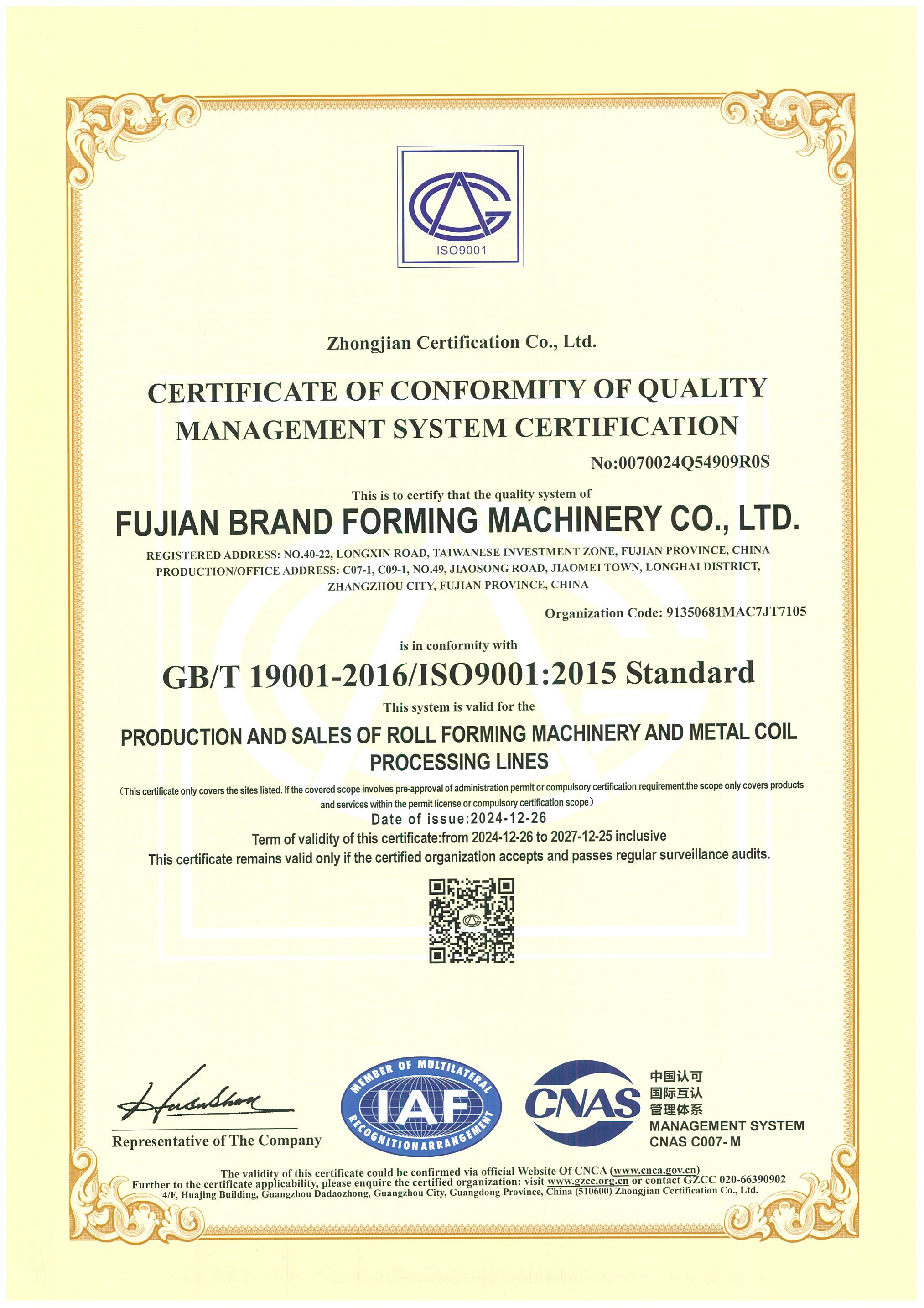 ISO 9001:2015
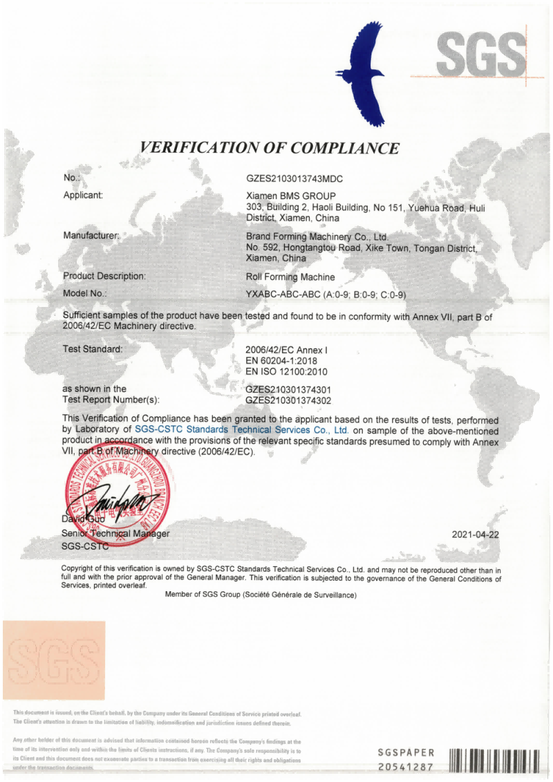 CE Machinery Verification
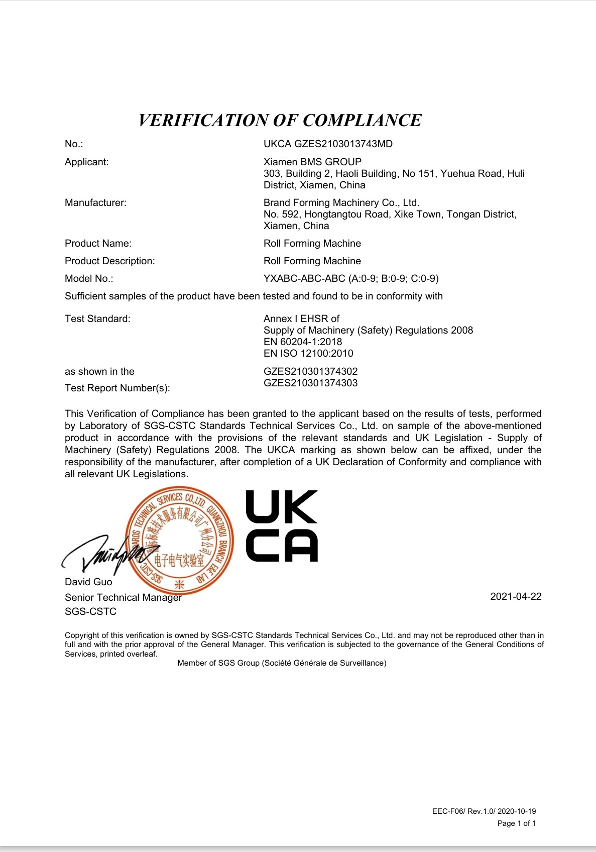 UKCA Machinery Verification
Two-Year Warranty and Overseas Support
BMS provides a two-year warranty for parts and labor, starting from successful installation and commissioning at the buyer’s site, subject to correct operation and maintenance.
Six overseas service centers support BMS machines, with regional service in South Asia, the Middle East, South America, North America, Europe and South Korea. Technical support continues throughout the machine’s service life.
Overseas installation is chargeable. The buyer provides visa assistance, return airfare and local accommodation. Include the applicable service charges, warranty exclusions and support arrangements in your quotation.
Read BMS service terms →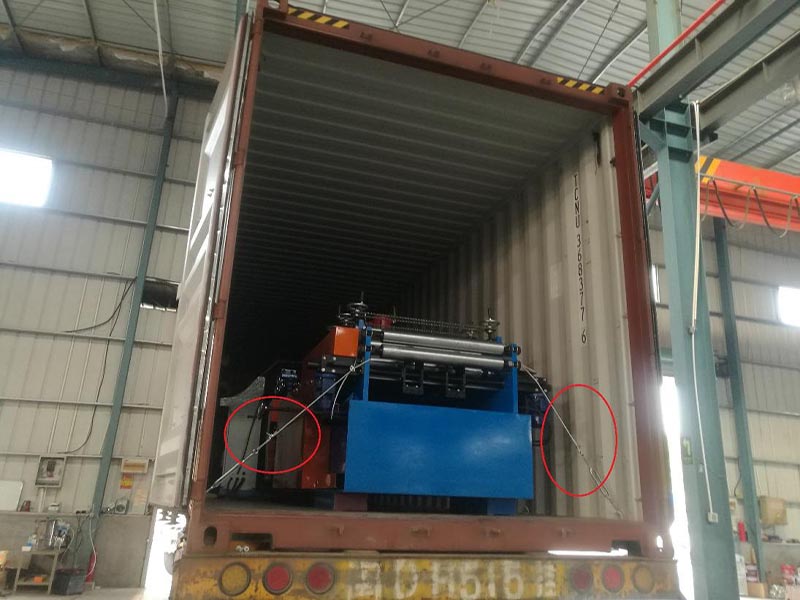
Workshop Readiness
Plan unloading and the working layout using the full line dimensions, electrical supply and connection requirements. A motor rating alone does not specify the site power connection.
Name the site coordinator and qualified connection provider, and allocate their work before arrival.
Commissioning Trial
Run functional checks and start-up samples with the selected drawing, actual coil and a representative cut list. Record the observations and acceptance conditions required for release into production.
Define who attends, the supplier’s assistance, the method and scope, charges and the handover condition.
Operator Training
Set out the operator and maintenance tasks, training language, delivery method and machine files. Identify the trainer and attendees in the training record.
Keep machine operation and maintenance training separate from roof-system installation or engineering instruction.
Parts and Support
Identify wear parts, supplied spares and the support contact in the written terms.
Keep the machine identification, maintenance record and fault images or video ready for technical support. Retain the service contact and any chargeable work in the handover file.
Your Production Handover File
- Confirmed configuration and drawings, with the acceptance record
- Operating, electrical and maintenance files, plus wear- and spare-part identification
- Training record and written warranty and support terms
Questions About Your Production Line
Answers to the configuration and commercial questions that can change the equipment choice.
Changing cut length does not change the profile. Another width, rib or seam needs a tooling and configuration review against its own drawing.
Compare length and profile changesBMS offers standing-seam lines configured in 20 ft or 40 ft containers for site production. Select that configuration separately from a fixed-workshop line, with suitable access, power, crew, weather protection and long-panel receiving.
Compare production locationsThe YX65 comparison covers color steel at 0.4–0.80 mm and Al-Mg-Mn aluminum at 0.8–1.2 mm. Match the steel yield grade or aluminum alloy and temper, coating and feed width to the selected profile and tooling; similar thickness alone is not enough.
Review the coil inputsBMS supplies automatic size-changing curving equipment with taper capability and automatic tapered-sheet slitting equipment. These are selected process configurations: a cut-length change cannot create curvature or taper. Include the final geometry, seam detail and the required forming, slitting, curving and receiving interfaces in the brief.
Review special geometryNo. Machinery conformity documents address the equipment. Roof wind and water performance needs evidence for the specified roof assembly and project.
See the responsibility handoverBring the same panel drawing, coil data, cut list and destination to each quotation. Compare equipment, auxiliary handling, acceptance, documents and after-sales responsibilities on the same basis.
Check the supply and handover scopePlan Your Roof Panel Production with BMS
Bring your panel drawing, coil specification and a representative cut list to the discussion. Together, these define the roof panel roll forming machine, supporting equipment and acceptance requirements to compare.
Discuss Your Production RequirementsPrepare Your Production Brief
- Target panel and connection drawings
- Coil grade, thickness, strength basis, coating and width
- Typical cut list, quantities and positioned features
- Longest panel, workshop and dispatch conditions
- Destination country and required project documents