


BMS · Sunroom accessory manufacturing
Roll Forming Machines for Sunroom Gutter and Roof Trim
Gutter, ridge cap and trim profiles for sunroom roof systems.
Select a gutter roll forming machine and the appropriate ridge cap and trim equipment from each finished profile, its coil specification and your order mix.
Map Your Sunroom Roofing Components
Start with the position and mating surface of each part. Five component types can belong to the same roof while requiring different geometry, tooling and finishing operations.
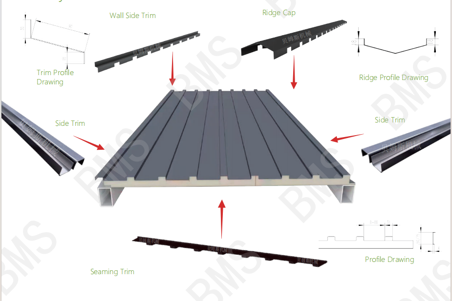
The layout shows the ridge, wall junction, sloping roof edges and profiled-board closure. Match each part to your roof-system drawing; eave gutter and gable trim serve different positions.
Open the full-size imageAt the eave
Spanish Gutter
Mating surface. Eave, fixing edge and outlet arrangement. Drainage capacity follows the roof design.
Geometry to define. Gutter section, attachment lips, returns and finished length
Connection details. End caps, outlet openings, joints and brackets
Drawing to supply. Dimensioned section plus fixing/end details for workshop Spanish-gutter production. A portable K-style machine follows a different profile and workflow.
Roof-board accessory
Ridge Cap
Mating surface. Both roof faces beside the ridge
Geometry to define. Angle, wings, returns and panel interface together. Overall width alone cannot define fit.
Connection details. Overlap, fixing and adjacent panel shape
Drawing to supply. Both mating roof sections and complete cap drawing; the roof design sets the angle.
Roof-board accessory
Sidewall Trim
Mating surface. Wall junction and adjoining roof panel
Geometry to define. Wall leg, roof-side leg, returns and laps; distinguish sidewall from endwall flashing on the drawing
Connection details. Fixing and wall/roof connection
Drawing to supply. Section and complete wall-junction detail, identifying the two mating sides.
Roof-board accessory
Gable (Rake) Trim
Mating surface. The sloping gable/rake edges shown on this roof; check left and right parts separately
Geometry to define. Left/right sections, returns and fixing geometry; an eave trim serves a different roof edge
Connection details. Side laps, fixing points and end details
Drawing to supply. Separate left/right drawings and panel details. Repeated names do not establish shared tooling.
Roof-board accessory
Panel Closure Trim
Mating surface. The ribs and valleys at the specified profiled roof-board edge
Geometry to define. Matching rib/valley shape, closure geometry and lengthwise features
Connection details. Connection at the profiled edge; any holes or local features
Drawing to supply. Complete closure drawing and mating board sample, including local features and attachment details. A roof seamer locks a designed seam; this closure is a separate component.
Match the Profile, Coil and Tooling
Match the complete finished profile and actual coil specification before choosing tooling. Folds, mating dimensions and material define the configuration.
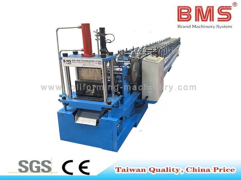
YX132-172 · H450 configuration
YX132-172 Spanish Gutter
This specification covers the H450-frame configuration with a Cr12MoV cutter. Match your gutter section, coil certificate and finished-part requirements before ordering.
- Material
- 201 stainless steel
- Thickness
- 0.5–0.8 mm
- Yield strength
- 260–310 MPa
Assess outdoor corrosion suitability separately. Changes in grade, yield strength, thickness or coating require a new tooling and cutting assessment.
YX132-172 Technical SpecificationsFrame, rollers, cutting, electrical options and coil handling
This workshop gutter configuration is specified for 201 stainless steel. Check your complete section, material certificate and finished-part requirements before choosing the line.
Review the YX132-172 Spanish Gutter Roll Forming Machine product specification. Select the electrical supply, controls and complete line scope for your quotation.
| Technical item | Configuration and selection conditions |
|---|---|
| Profile and material | |
| Material and working window | 201 stainless steel; thickness 0.5–0.8 mm; yield strength 260–310 MPa |
| Feed width and finished dimensions | Set from the approved YX132-172 section drawing; feed-coil width and finished width are separate dimensions |
| Forming mill | |
| Body frame | H450 H-section steel; welded, levelled and stress-relieved |
| Forming rollers | GCr15 steel; hardened and hard-chrome plated |
| Forming stations | 21 steps |
| Shaft diameter | 65 mm |
| Forming speed | About 10–15 m/min |
| Main motor | 7.5 kW |
| Cutting system | |
| Cutter pump motor | 4 kW |
| Post cutter | Cr12MoV steel |
| Cutting tolerance | ≤ ±1 mm; agree the measured feature, trial material and sample procedure |
| Electrical supply and controls | |
| Electrical supply | 220, 380, 415 or 480 V; 50 or 60 Hz; three phase. Select one compatible supply in the quotation. |
| Inverter options | Schneider Electric, Siemens or DELTA; agree the supplied brand and model |
| Touchscreen options | Schneider Electric, Siemens or WEINVIEW; agree the supplied brand and model |
| Encoder options | OMRON or KOYO; agree the supplied brand and model |
| Drive and PLC specification | Define the transmission arrangement and PLC make/model in the equipment proposal |
| Coil handling and line scope | |
| Decoiler and exit rack | Define coil capacity, inside diameter, loading method, exit-rack length and quantity in the equipment proposal |
Forming speed describes travel through the forming mill; accepted finished-part output also depends on cutting, coil changes, handling and the agreed trial window. The 7.5 kW main motor and 4 kW cutter pump are separate items, not a stated total line electrical load.
Machine formability does not establish outdoor corrosion suitability. Select 201 stainless steel for your roof environment and service requirement separately. A change of grade, yield strength, thickness or coating requires a new tooling and cutting assessment.
Before choosing the tooling
Prepare the Drawing and Coil Data
Finished profile
Supply the complete section, finished dimensions, feed width and every hole, notch, return or bend.
Material and coil
State grade, thickness, yield strength, finish, feed width, coil weight and inside diameter; review bend radii and springback.
Each component separately
Use a drawing revision for each component and handed trim; identify lengths, mating parts, finish and the production route.
Drawing, coil and profile-by-profile requirements
Select tooling from the complete finished profile and actual coil specification. A name such as “gutter” or “trim” is a starting point; the folds, mating dimensions and material determine the manufacturing configuration.
Profile Geometry and Finished Dimensions
Keep overall finished width, installation dimensions and feed-coil width separate. The developed width depends on the complete section and the forming process. Hems, returns and curves change roller and cutter requirements; a hole or notch may introduce another operation.
Material, Finish and Coil Data
Specify grade, thickness, yield-strength range, surface finish, coating or protective film. Add feed width, coil weight and inside diameter. Review bend radii and springback against the actual coil; equal thickness does not make materials interchangeable for the same roll set or cutter.
A Separate Specification for Every Component
Assign a drawing revision to each part, including handed trims. Record length range, mating component, surface requirement and the candidate machine or process. A gutter specification cannot establish the working range of the ridge or closure parts.
Spanish gutter
Drawing and geometry: Attachment edges, returns, curves and outlet/end details
Material and coil: Grade, thickness, strength, finish, feed width and coil weight/ID
Order, interface and process: Lengths, batch quantities, mating supports and the gutter forming/cutting configuration
Ridge cap
Drawing and geometry: Angle, wing widths, hems and mating roof faces
Material and coil: Its own material, finish and developed coil width
Order, interface and process: Lengths, roof interface and a ridge forming or bending route
Sidewall trim
Drawing and geometry: Wall/roof legs, laps, folds and fixing details
Material and coil: Its own material and developed width
Order, interface and process: Junction drawing, local holes/notches and the forming/finishing sequence
Gable (rake) trim, left/right
Drawing and geometry: Handed geometry, returns and fixing edges
Material and coil: Specify each handed part; assess whether coil data can be shared
Order, interface and process: Separate drawings, changeover requirements and simultaneous demand
Panel closure trim
Drawing and geometry: Closure shape matching the profiled board; longitudinal features
Material and coil: Material and feed conditions for the chosen route
Order, interface and process: Board sample/drawing, feature sequence and required finishing tools
Specify the body frame, cutter material and coil working window in your equipment quotation, then use that configuration for the drawing approval and production trial.
Choose Which Components to Produce In-House
Bring stable, repeat components in-house when the drawings, demand and workshop resources support it. Add other routes in stages, while retaining existing processes or outside supply for changing and occasional parts.
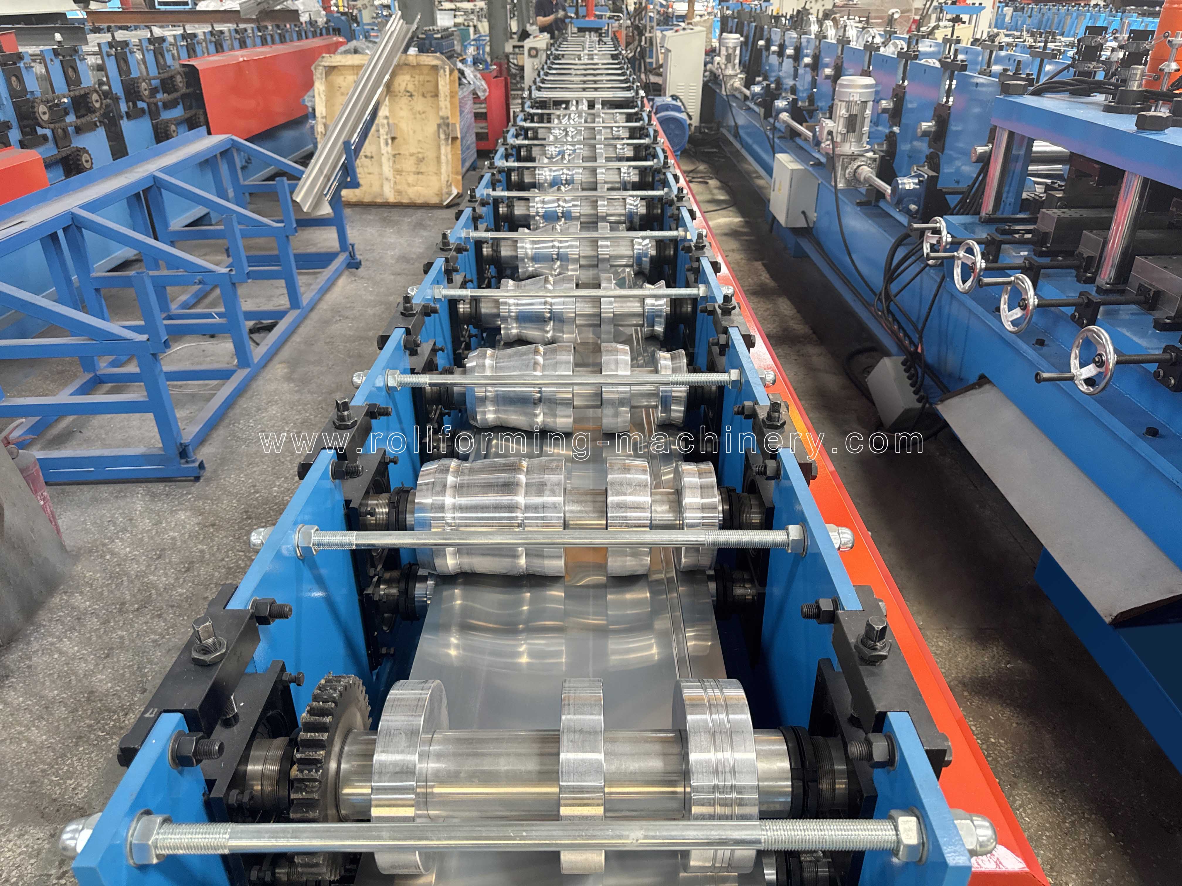
One workshop can use more than one production route.
Make a stable component in-house
Repeat orders, a settled drawing and a clear supply bottleneck. A settled gutter section and purchased-supply delays make this a first candidate. Check that the workshop can handle both coil and finished lengths. If the design is changing or orders are infrequent, resolve that variability first.
Gain: More control of that part’s schedule. Allow for: Coil stock, operators, tooling and receiving/packing resources.
Defer investment until demand, profile fit and workshop conditions are sufficiently defined.
Add equipment in stages
Several repeat profiles with different demand patterns. Compare dedicated tooling with a compatible multi-profile machine. Check the exact profile list, tooling arrangement, changeover steps and parts made after a changeover. Independent resources may suit simultaneous orders; shared equipment needs an achievable batch sequence.
Gain: Align investment with the next recurring production need. Allow for: Extra space, shared handling and either changeover or parallel-line planning.
Check each profile’s tooling, changeover time and the parts produced after setup.
Use existing processes or outsource
Low-volume, changing or project-specific trims. Existing bending or other processes and outside supply can coexist with a gutter line. Check actual material, length and geometry; reducing machine count alone does not establish production fit.
Gain: Retain flexibility while the profile mix changes. Allow for: Outside lead time, coordination and checks; existing process capacity.
Assess geometry/material feasibility and total supply timing before committing.
Let the order mix set the investment sequence.
Bring your profile list, order frequency, outside waiting time, coil inventory and operator/handling capacity. Identify simultaneous components and those that can be batched, then compare a complete supply-scope quotation against your order history.
Discuss Your Component MixFollow the Gutter Production Route
The gutter manufacturing machine route runs from decoiling and feeding through profile forming, post-cutting and receiving. Every handoff must suit your coil, section and finished length.
Open the original image for a closer view. Wide drawings can be scrolled sideways.
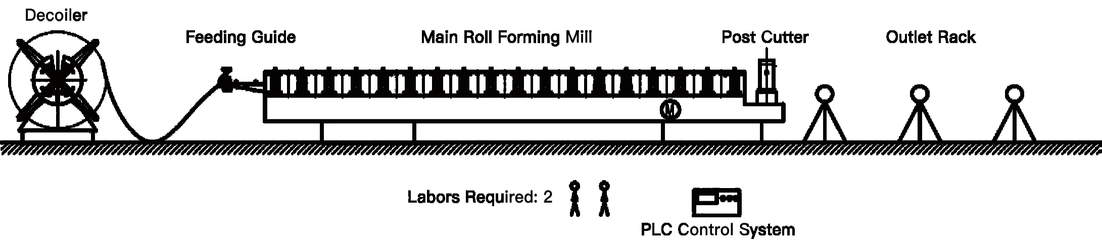
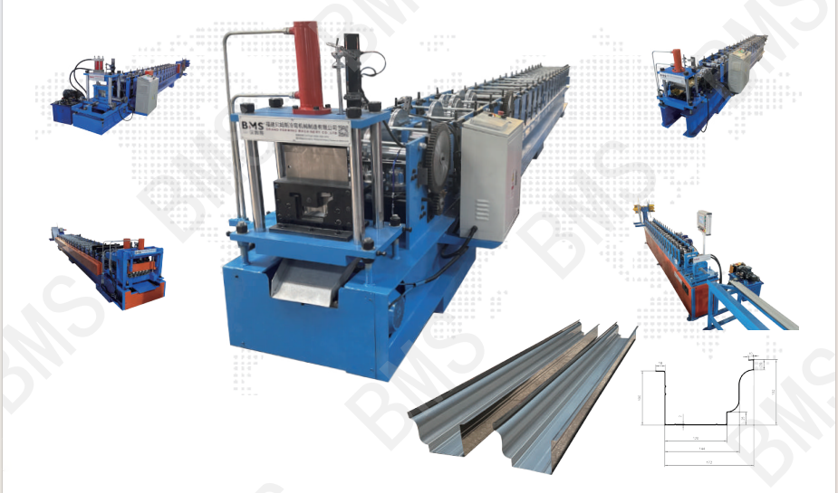
Spanish gutter profile and line illustrations
Open the original image for a closer view. Wide drawings can be scrolled sideways.
- 01
Decoil
Load the coil specified for the selected feed arrangement; match coil weight, width and inside diameter.
- 02
Guide and feed
Present the strip to the forming mill in the required position and condition.
- 03
Roll form
Progressively form the approved gutter cross-section with its assigned tooling.
- 04
Post-cut
Cut the formed section to the order length with the applicable cutter and length-control arrangement.
- 05
Receive and pack
Support the finished gutter, check it and move it through packing without obstructing the outlet.
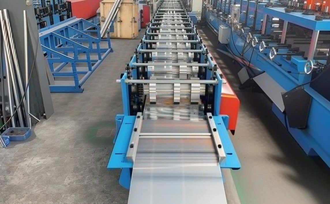
Coil Supply and Feeding
Check the material and coil dimensions against the feed arrangement before comparing automation. The coil-loading method, guiding and available floor space have to work together. A different finish or material condition also belongs in the trial rather than being treated as the same input.
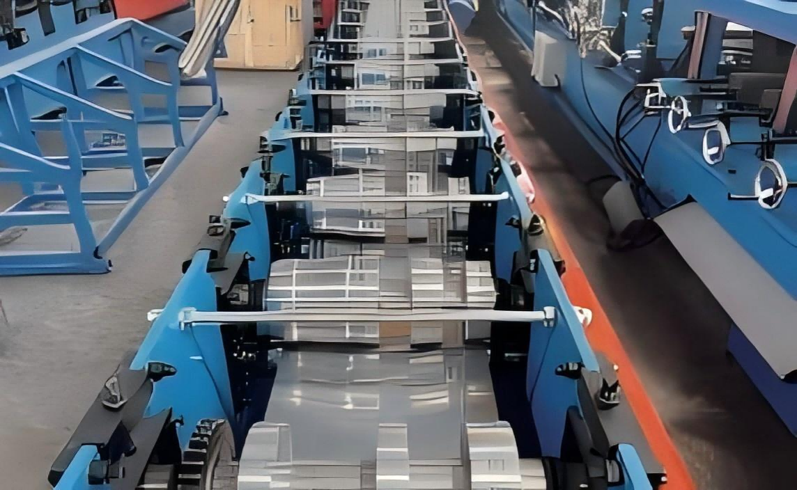
Forming the Approved Profile
A change in finished length calls for a length-control and receiving review. A different cross-section calls for tooling review. Producing several lengths of the same profile does not automatically require another roll set; changing the cut length cannot produce a different section.
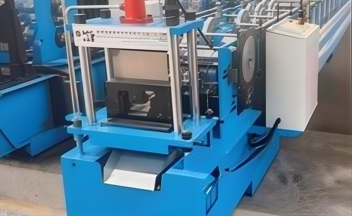
Cutting, Receiving and Packing
Match the cutter and end support to the section, then compare receiving and packing with your batch sizes. A mill running continuously can still be limited by cutting, inspection or outlet handling. Evaluate the complete route against delivered good parts.
Define what happens after the straight gutter is formed. Assign end caps, drainage openings, joints and brackets to the line, another process, your workshop or an outside supplier. Include their equipment, drawings and handling interfaces in the supply scope. Specify automatic decoiling, stacking or any additional operation as a separate configuration item.
Define the Manufacturing Route for Ridge and Trim Parts
Separate the continuous cross-section from holes, notches and local closure features. That distinction determines which part of the work belongs to roll forming and which needs another operation.
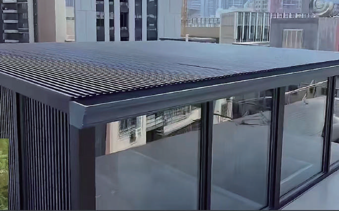
Repeated Cross-Sections
A long part with the same cross-section throughout is a roll-forming candidate when its geometry, material and demand fit the tooling. Compare a dedicated route with compatible multi-profile tooling, taking part length and surface contact into account.
Project-Specific Bends and Dimensions
For changing angles, wings or returns, compare a suitable bending process with dedicated or adjustable forming equipment. In a fixed-angle roll set, the rolls determine the ridge angle. List every roof pitch and confirm whether the proposed machine needs replacement tooling or has an adjustable forming arrangement; do not assume changing the cut length changes the angle.
Features Along the Part Length
Holes, notches and a closure shape matching the profiled board can change the process sequence. Identify whether each feature is made before forming, after forming or in a separate operation. A cross-section drawing alone cannot define every finished-part feature.
Ridge-cap production
YX130-502 Ridge Cap Roll Forming Machine
Match the ridge section, coil grade, strength and roof angle to your drawing and trial.
View YX130-502 Brochure (PDF · 2 pages)- Material
- Aluminum-zinc-coated steel (GL) or PPGI coil
- Material thickness
- 0.36–0.5 mm
- Forming speed
- 15–20 m/min
- Forming stations
- 12
- Main motor
- 5.5 kW
- Roller material
- 45# steel
Forming speed is strip travel, not accepted output. The tooling determines the roof angle; changing cut length does not change it.
Manufacturing tasks for ridge and trim parts
Ridge cap
Define the finished part: Roof angle, wings, folds and hems; End detail, overlap or local features.
Manufacturing route: Roll forming or a suitable existing bending process.
Approve the formed angle and both mating roof faces using the actual coil; agree tooling changes for every required pitch.
Sidewall trim
Define the finished part: Wall/roof legs and junction geometry; Fixing holes, notches, laps or local changes.
Manufacturing route: Profile forming plus any required punching/bending/finishing.
Establish the sequence and access for every feature.
Gable (rake) trims
Define the finished part: Left/right cross-sections and returns; Fixings, notches and end details on each handed part.
Manufacturing route: Dedicated, shared or existing process according to the drawings.
Assess mirrored tooling, changeover and simultaneous orders.
Panel closure trim
Define the finished part: Closure geometry against the profiled board; Rib/valley matching, local shape and lengthwise features.
Manufacturing route: Separate the base section from any additional shaping operations.
Use the mating board and complete finished-part drawing.
Related Machines for Sunroom Accessory Production
Compare these gutter, ridge and trim machines against your component drawings and coil specifications. Dedicated roll forming, shared tooling and sheet bending serve different production tasks.
Roll forming · Gutter
YX132-172 Spanish Gutter Roll Forming Machine
Workshop Spanish-gutter production: 201 stainless steel, 0.5–0.8 mm and yield strength 260–310 MPa; 21 forming steps; about 10–15 m/min.
Profile & Coil FitH450 body frame, GCr15 rollers and Cr12MoV cutter. Confirm your section and selected line options against the YX132-172 specification above.
View machine details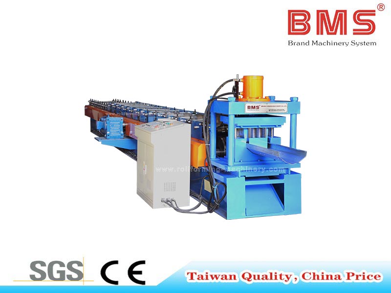
Roll forming · Gutter
Seamless Gutter Forming Machine with Optional Punching
Galvanized sheet, 0.25–0.55 mm; 18 forming steps; forming speed 12–15 m/min and main motor 11 kW.
Profile & Coil FitMaterial strength designation: G450–550. Confirm the coil grade and material certificate, gutter section, hole pattern and whether optional punching is included.
View machine details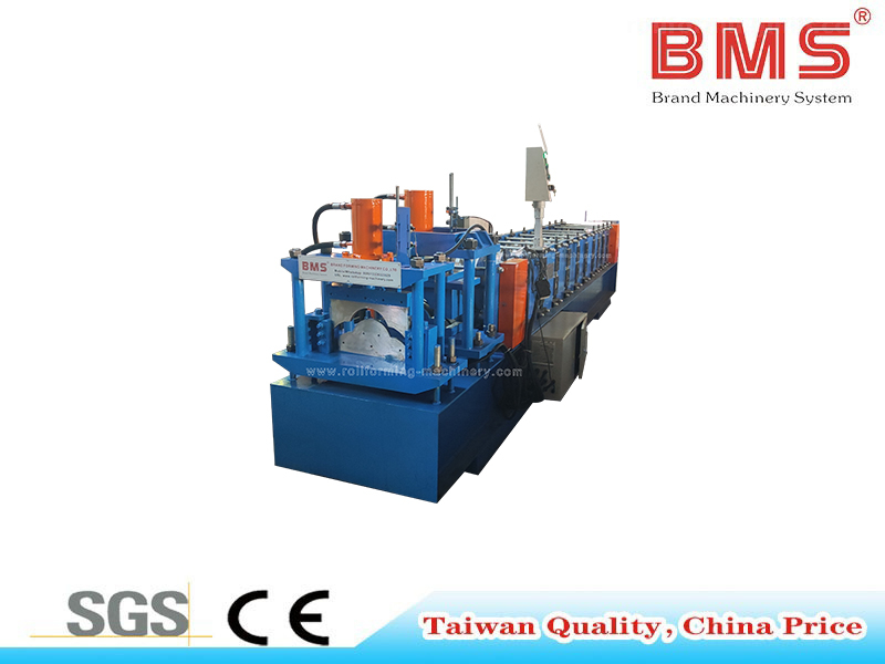
Roll forming · Ridge cap
Metal Roof Ridge Cap Roll Forming Machine (Philippines Model)
Galvanized coil or prepainted galvanized steel (PPGI), 0.3–0.8 mm; yield strength 245–450 MPa; 12 forming steps; 18–20 m/min.
Profile & Coil FitPhilippines model: H400 body frame and 5.5 kW main motor. Specify roof pitch, roll-set or adjustment arrangement, wings, returns and mating roof faces.
View machine details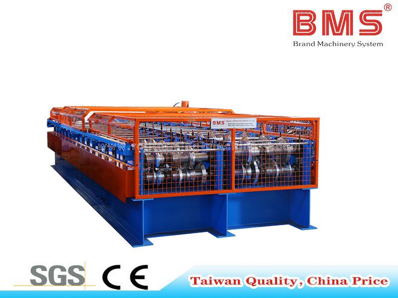
Roll forming · Multiple trims
Professional Trim Roll Forming Machine — Four Profiles
Choose four profile families from eleven available choices. For the corner, V-valley, ridge cap and L-trim set: galvanized coil or PPGI, 0.5–0.7 mm, at 220 MPa yield strength; 16/16 forming steps and 12–15 m/min.
Profile & Coil FitSpecify four actual section drawings before quotation. Agree the tooling arrangement and changeover sequence for your selected profiles.
View machine details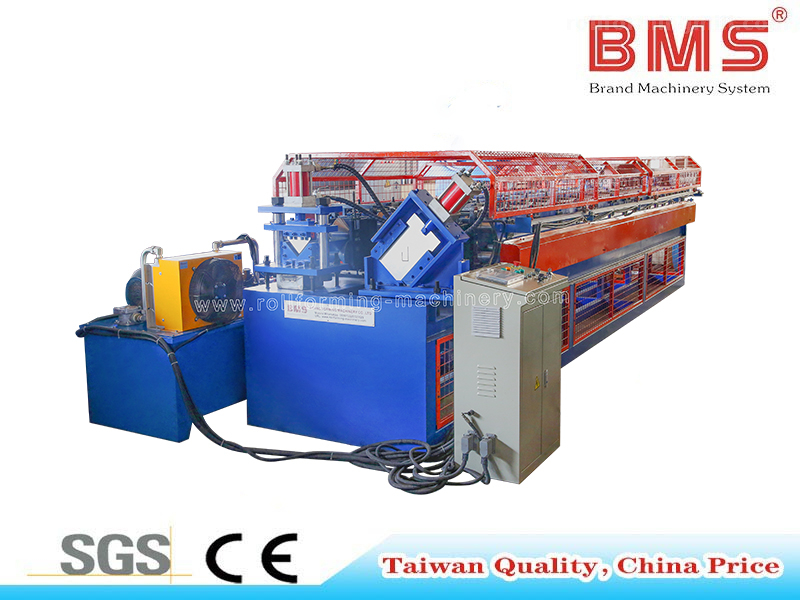
Roll forming · L / J trim
L and J Trim Roll Former
Two-in-one L/J trim equipment: galvanized sheet, 0.4–0.6 mm; yield strength 235–345 MPa; 14/12 forming steps and forming speed 25 m/min.
Profile & Coil FitH450 body frame, GCr15 rollers and Cr12MoV cutter. Match both section drawings and sidewall or roof-edge interfaces; an L or J name alone does not establish fit.
View machine details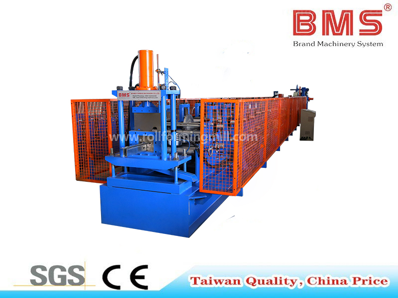
Roll forming · Gable trim
18-Station Gable Trim Roll Former with Safety Guarding
Galvanized or cold-rolled sheet, 0.4–0.6 mm; yield strength 235–345 MPa; 18 forming steps and forming speed 25 m/min.
Profile & Coil FitH450 body frame with lifting rings and Cr12MoV cutter. Compare the section with your left/right gable drawings, end details and fixing features.
View machine details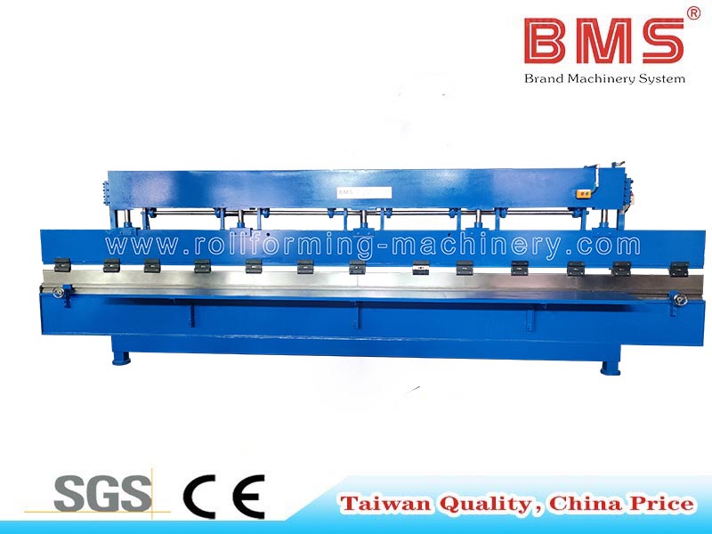
Sheet bending and folding
6.2 m Metal Sheet Bending Machine
Sheet bending for roof trims, ridge caps, gutters and flashings with changing project geometry.
Bending RequirementsConfirm usable bending length, material, bend radius, tool access and the complete bending sequence before comparing it with roll forming.
View machine details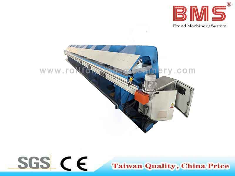
Sheet bending and folding
8 m Long Folder Slitter
Long-sheet folding and slitting for changing sections.
Bending RequirementsCompare finished length, material, bend radius, clamping and the required working layout.
View machine details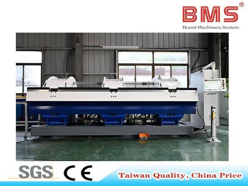
Sheet bending and folding
Double Bending Slitter Folder
Double bending and slitting for sections requiring bends in both directions.
Bending RequirementsCompare the complete bend sequence, tool clearance and actual material before selecting this folding configuration.
View machine details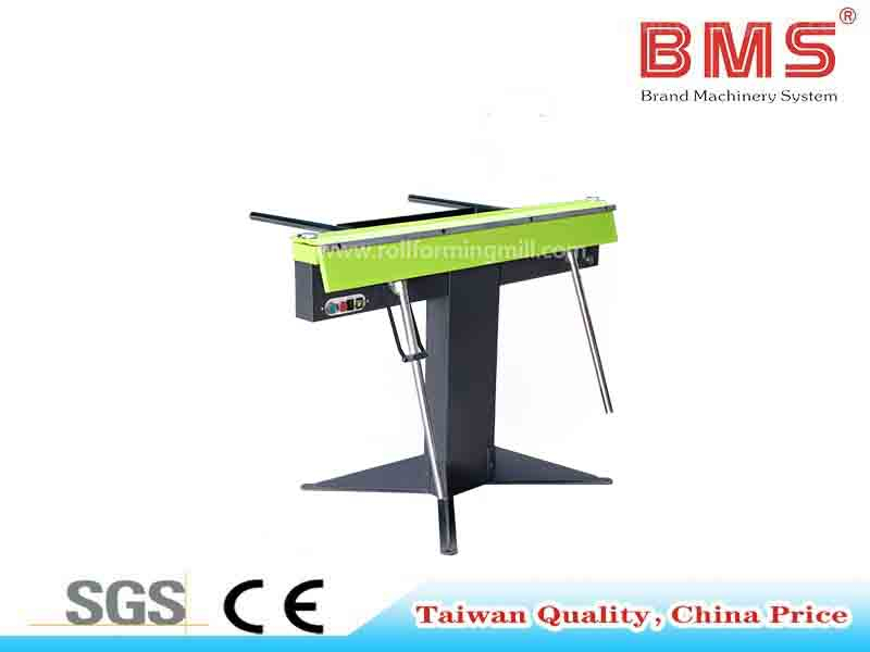
Sheet bending and folding
1250B Electromagnetic Metal Bending Machine
Manual sheet bending with electromagnetic clamping for shorter trim details or trial bends.
Bending RequirementsCheck the required working length, material and tooling against the specific 1250B configuration.
View machine details
The four-profile machine offers corner, rake, ridge cap, eave trim, angle trim, Z trim, J-channel, V-valley, W-valley, fascia and snow guard families. Choose the four required profiles and agree their exact sections, tooling and changeover arrangement. Use the YX132-172 gutter specification and finished-part and mating-board drawings to compare the routes for your workshop.
Evaluate Output Against Your Order Mix
Compare accepted finished parts over a defined elapsed time, using your actual lengths and batch sequence. Rated forming speed, running speed with cuts and ready-to-deliver output answer different questions.
Use your trial record
Calculate your good-part output
Enter accepted output and the same elapsed evaluation window you use to compare configurations.
This result uses your entries. The YX132-172 forming-speed value is a different measure.
Use the same basis for every comparison
Measure accepted output over the whole agreed trial window.
Choose representative short and long parts and small repeat batches, with the approved drawing revision, actual coil and required handoffs. Record accepted lengths or pieces, rejects, trial material and start-up scrap.
Record actual start/finish times, coil loading, tooling changes and cutting stops. Activities may overlap; do not add their individual durations to estimate elapsed time. State whether receiving, inspection and packing are included or reported separately.
Good-part output = accepted quantity or length ÷ elapsed evaluation time. The YX132-172 model’s about 10–15 m/min is forming speed, not the delivered output of your order.
Prepare the cut list for your trial
Keep one record per drawing, material and finished length. Use your actual quantities and trial data to calculate accepted output over the agreed elapsed time.
Spanish gutter
Drawing and coil record: Part code, approved drawing revision and coil specification
Order record: List each finished length and required quantity
Sequence and checks: Batch order, coil changes, cutting and receiving checks
Ridge / sidewall trim
Drawing and coil record: A separate drawing and material record for each profile
Order record: List each length, quantity and repeat frequency
Sequence and checks: Tooling/route changes, local features and packing
Gable (rake) trim, left / right
Drawing and coil record: Separate handed-part records and mating details
Order record: List left and right quantities separately
Sequence and checks: Shared-machine sequence or parallel resources; handed-fit checks
Panel closure trim
Drawing and coil record: Complete closure drawing and corresponding roof-board record
Order record: List required lengths and quantities
Sequence and checks: Additional feature operations and the closure-fit check
Plan Coil Handling and Workshop Space
Plan the entire coil-to-dispatch path around the selected configuration and longest finished part. The main machine’s dimensions alone cannot define the workshop space or production resources.
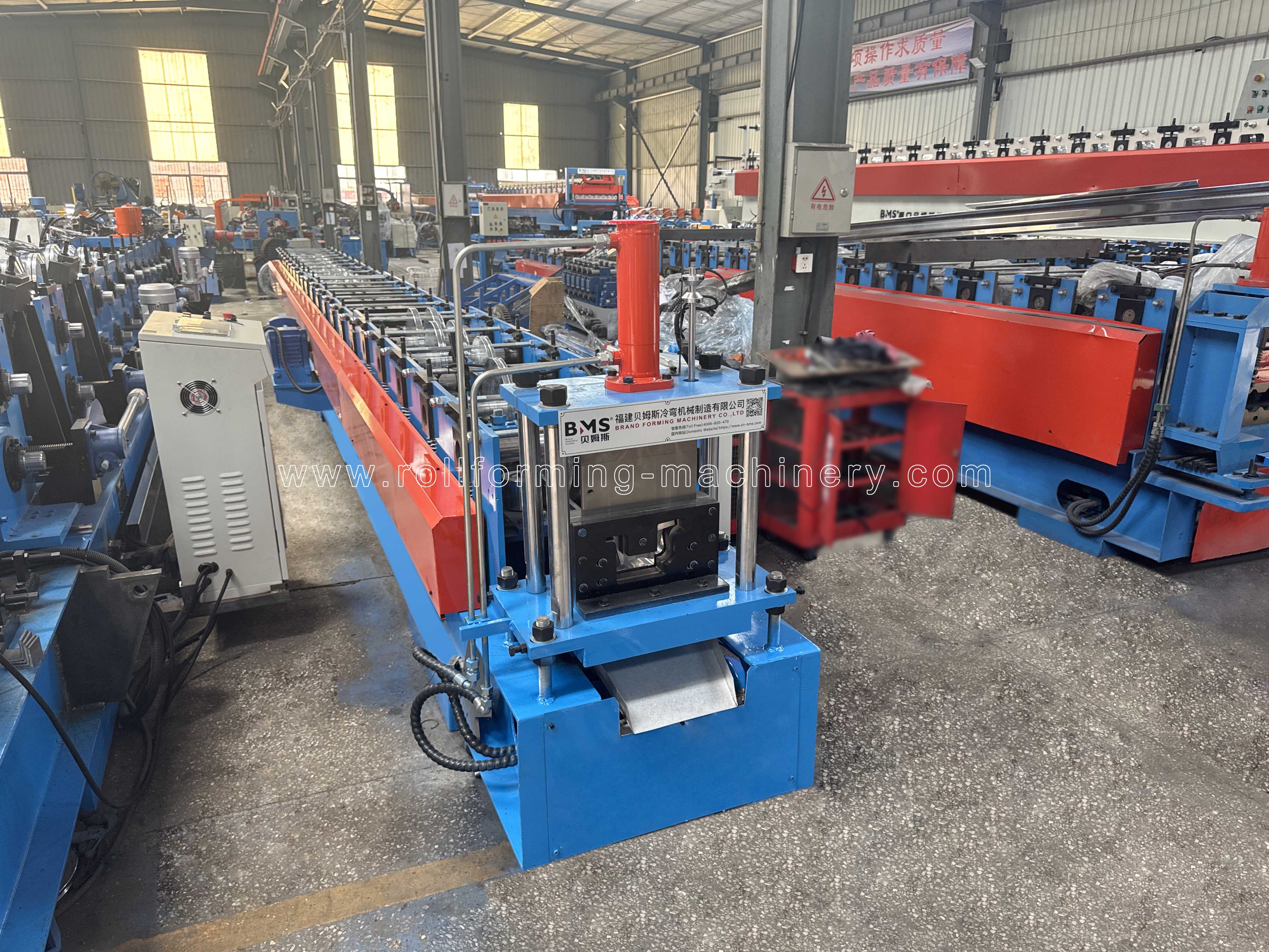
Coil storage → loading
Route incoming coils to the feeder without conflicting with active production or finished-part handling.
Forming → receiving
Lay out the selected equipment and the full receiving area for your longest gutter or trim.
Inspection → packing → dispatch
Keep accepted parts supported through checking, storage, packing and onward movement.
Before the layout is fixed
Plan the complete material path.
The longest finished part affects receiving, turning and packing space. Long or easily marked sections need appropriate support through each handoff.
The YX132-172 model’s 7.5 kW motor does not establish total line power, site connections or the complete footprint.
Coil storage and loading. Review Available floor route, coil stock location and handling method. Assess Coil support, loading interfaces and any new supply equipment. Bring Weight/width/ID, delivery path and loading approach.
Machine and utilities. Review Space, voltage, phase, frequency and connection points. Assess Selected line layout, total electrical demand and other required interfaces. Bring Working layout, access needs and configuration utility documents.
Outlet and long parts. Review Existing receiving supports and handling/inspection resources. Assess Longest-part support and onward movement to packing. Bring Maximum finished length, shape, finish and turnaround path.
Shared resources. Review Operators, material handling and packing used by other equipment. Assess Dedicated resources where simultaneous production needs them. Bring Conflicts between loading, line operation and dispatch.
Define Profile, Fit and Finish Acceptance
Agree the drawing, actual coil, measurement methods and acceptance limits before production trials. Review the forming sequence and springback, approve the first article and define the factory acceptance test (FAT) before shipment.
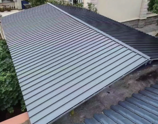
Keep the drawing revision, actual coil identity and finish, machine configuration, representative order and trial conditions with every sample.
Agree measurement locations, gauges, sample quantity and allowable deviation before the trial. A successful interface trial covers that interface; the complete roof’s waterproofing and structural design remain roof-system decisions.
During technical review, request the forming pass schedule or roll-flower review relevant to your section, with the document scope agreed in the proposal. Discuss bend radii, springback compensation, profile-specific tooling and any punching or secondary operations.
Agree first-article approval and a pre-shipment FAT using identified coil, representative lengths and quantities, agreed gauges and recorded results. Define how deviations are corrected and retested and who signs the release; keep site commissioning as a separate handover step.
Profile dimensions and angle
Approved revision, actual material and nominated datums. Named dimensions/angles, agreed gauge or measurement method. Record limits, sample quantity, measured results and responsible reviewer.
Mating fit
Corresponding board, roof faces or wall/side interface. Trial assembly against the specified mating part. Record the tested interface and its agreed fit criteria.
Length, bow, camber and twist
Representative long and short parts; common measurement basis. Measure length, out-of-plane bow, in-plane camber and twist separately, with agreed support, datum, test length and method. Set a limit for each measured feature and record the first-article and FAT results; do not apply the cutter tolerance to every profile dimension.
Cut edge and end shape
Full section and cut-end samples under the specified material condition. Inspect the defined edges, deformation and end geometry. Compare with agreed sample/criteria; retain images and part identity.
Surface and finish
Incoming coil reference and finished/packed part samples. Compare surfaces before/after processing and handling. Agree finish criteria, observation points and the retained records.
Compare Quotations on the Same Supply Scope
Compare the same drawings, process boundary and delivery/service scope. A useful quotation identifies what is included, what is optional, what you already own and who handles each interface.
One scope for every quotation
Define what your investment includes.
Freeze the drawings and proposed configuration. One related machine’s price cannot represent the complete sunroom accessory production package.
Use the same process start/end points, destination and onsite responsibilities. Include existing equipment interfaces so necessary support is neither missed nor purchased twice.
Classify every supply item and name who owns the interface.
Ask the quotation to identify the contracting supplier, ordered machine quantity, selected tools and inclusions. Agree the delivery lead time from defined milestones such as drawing approval, payment and availability of trial coil; specify the delivery basis and destination. Compare training, spare parts and warranty on that same scope.
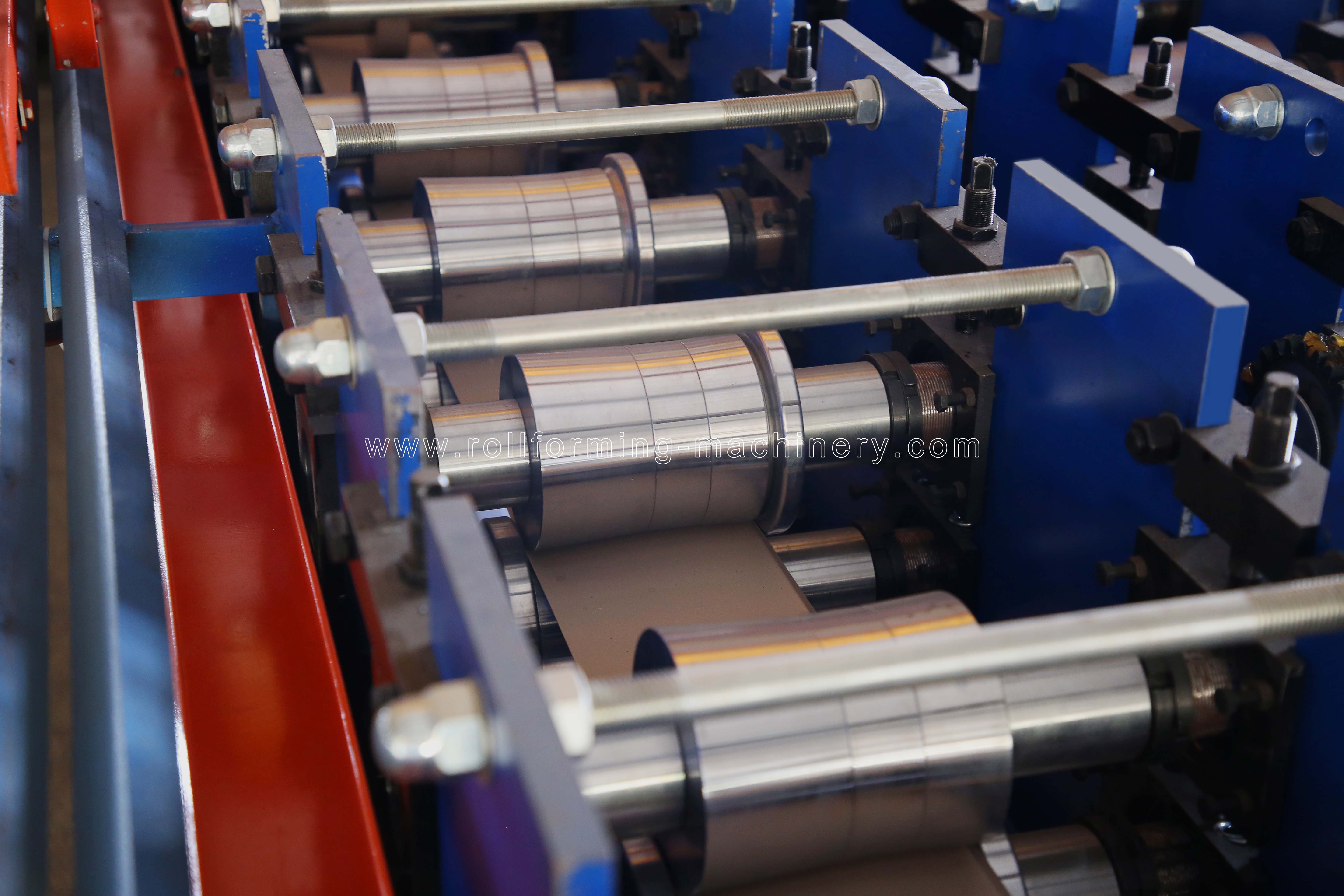
Compare equipment, interfaces and commercial scope
Main equipment and tooling
What to compare: Machine, exact profile tools, changeover items and configuration
Scope classification: Identify included / optional / buyer-owned items
Supporting input: A drawing-to-tooling list for every component
Coil supply and feeding
What to compare: Decoiling, loading, guiding and the interfaces to existing equipment
Scope classification: Assign equipment and interface responsibilities
Supporting input: Coil dimensions, handling method and layout
Cutting and receiving
What to compare: Cutter, length control, outlet support and any stacking/packing functions
Scope classification: Separate included functions from additions and existing resources
Supporting input: Part-length/shape requirements and trial scope
Downstream operations
What to compare: Openings, end caps, joints, brackets and local trim features
Scope classification: Assign each operation and its required equipment
Supporting input: Complete part details and process sequence
Documents, spares and service
What to compare: Agreed technical drawings/pass-schedule review, FAT records, operating and electrical manuals, machine-specific spare list, training and support
Scope classification: Name delivery, training, commissioning and cost responsibilities
Supporting input: Destination, document language and written service scope
Commercial terms
What to compare: Contracting company, machine/order quantity, payment milestones, lead-time start point, delivery basis, warranty scope and applicable charges
Scope classification: Compare the same destination and contract scope
Supporting input: The project’s written quotation and terms
For operating cost or payback, use your own material and scrap, labor, energy, consumables, inventory and outside-supply data, with a complete process boundary and order mix.
Prepare Delivery, Commissioning and Ongoing Support
Assign shipment, site readiness, commissioning, training and maintenance responsibilities before delivery. The handover should describe your configuration and destination rather than relying on a general export statement.
Configuration-specific handover
Make readiness, training and support part of the purchase.
Check destination-specific power, documents and site preparation against the selected configuration. Agree operator and maintenance participants, document language, training arrangements and any onsite charges in the proposal.
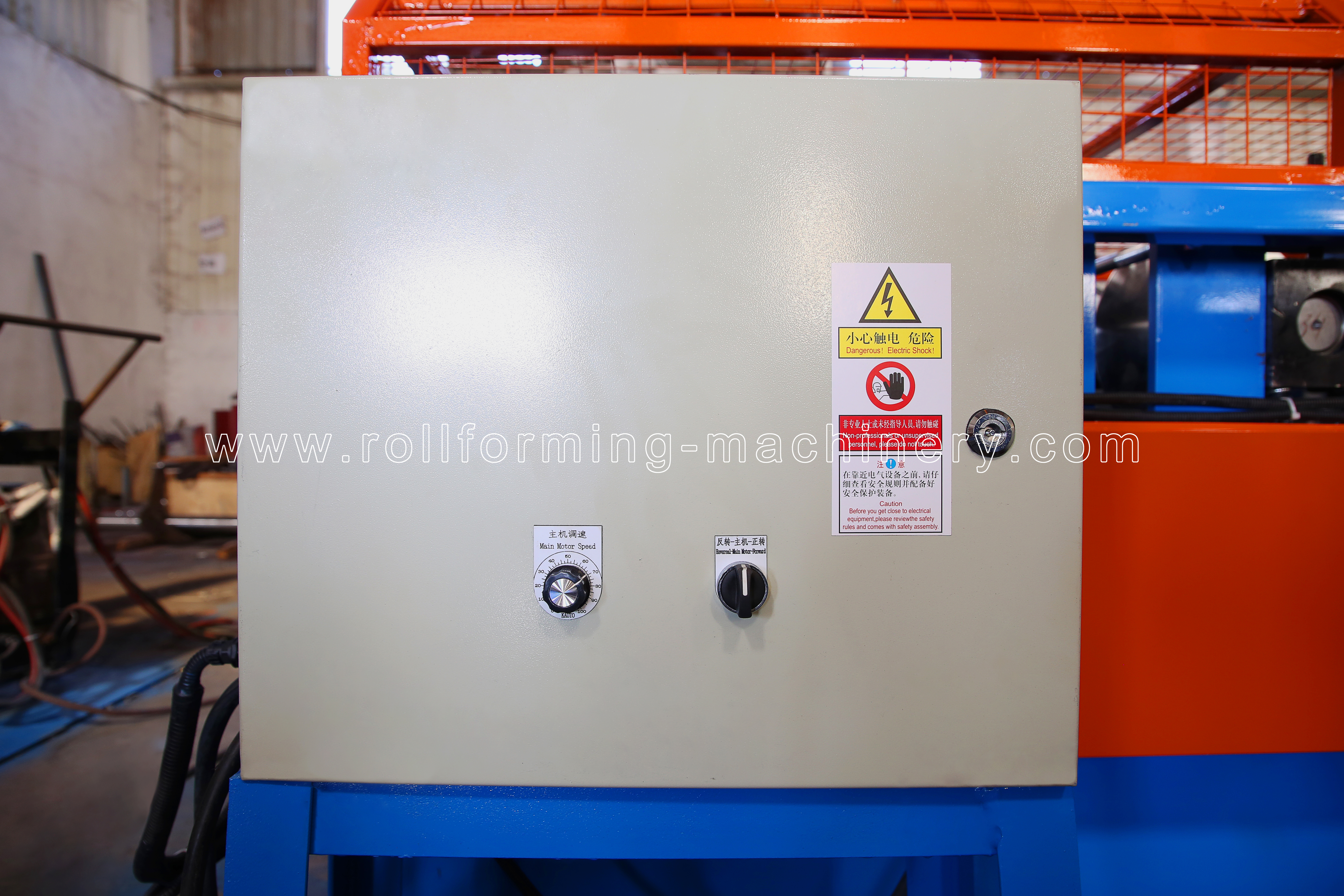
From shipment to operation
Agree the handover before shipment.
Keep the configuration, trial records and service scope together. Use the applicable machine instructions when operating or reporting a problem.
Shipment and unloading
Destination, delivery basis, package information and unloading arrangements. Shipping/packing record and suitable site unloading plan. Assign parties and charges before shipment.
Connections and commissioning
Selected electrical supply, layout, interfaces and readiness. Configuration and electrical information; commissioning scope. Assign site preparation, connection and trial duties.
Operator training
Operators, language, location/method and required tasks. Applicable operating information and training scope. Agree attendees, format, responsibilities and costs.
Maintenance and spare identification
Machine/tooling identification and planned maintenance information. Machine-specific spare list with part references, electrical components, wear items and operating/maintenance documents. Agree initial spare stock, ordering contact, replacement-part lead times and warranty inclusions/exclusions.
Acceptance and document handover
The actual configuration, trial conditions and agreed criteria. Approved drawing revisions, first-article and pre-shipment FAT results, correction/retest records and commissioning documents. Agree record ownership and the handover documents.
Reporting a problem
Machine identification, symptoms, coil and profile conditions. Images/video, material details and relevant operating observations. Use the applicable support channel and machine instructions.
Questions Before Selecting the Equipment
Resolve the profile and process questions that affect your equipment discussion.
One machine covers only its agreed profile set. For example, BMS’s four-profile trim machine offers a selection of four families from eleven choices; each actual section, material window and changeover arrangement must be agreed. Map all components and compare simultaneous demand before choosing shared or dedicated equipment. Review the related equipment.
A panel closure trim closes the specified profiled roof-board edge and must match its ribs, valleys and attachment details. A roof seamer mechanically locks a designed seam; it performs a different task. Define the closure’s forming and installation steps from the complete drawing rather than selecting a tool from the component name. See the roof component map.
Treat them as two parts. Send the left/right sections, dimensions and mating details, then establish whether reversible, mirrored or separate tooling is appropriate. Include the quantity and schedule for each handed part.
Only when every component’s approved material, thickness, strength, finish and feed-width requirements allow it. Check the feed equipment and coil dimensions too. Review the profile-by-profile coil inputs.
No. Compare drawing stability, demand frequency, outside waiting time and existing process capacity. A gutter line can coexist with existing processes or outside supply for occasional trims. Compare the three production routes.
Start the discussion with clearly labelled samples or photographs, key dimensions, the mating part and your material/length needs. Manufacturing and acceptance still require an accurate approved specification. Include left/right identification where it applies.
Your profiles. Your production plan.
Discuss Your Gutter and Trim Production Requirements
Share your profiles and workshop requirements with BMS to discuss equipment, manufacturing steps and supply scope.
- Your componentsDrawings or samples, revision, mating parts and left/right details.
- Your productionCoil specifications, part lengths, quantities and demand frequency.
- Your workshopExisting equipment, handling and utilities, destination and planned start.