


PALISADE FENCING ROLL FORMING MACHINE
Production of rails, posts and W-profile pales.
Configure a fence roll forming machine with BMS around your approved profiles, material and delivery stage.
On this pageOverview
Choose what you manufacture
Define the component family, order bill of materials (BOM), and delivery stage.
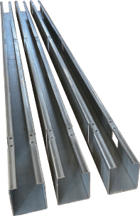
Rails & posts
Assess the twin rail/post task against the approved channel sections, lengths and connection features. Assign the rail, intermediate post and special post variants from the actual order BOM.
The working mode depends on feed, drive, cutting and take-off arrangements. Allocate each part to its actual path and tool set before scheduling the order.
Explore the twin rail/post system →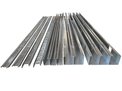
W-profile pales
Use the pale task for the approved W section. Specify the notch, holes, head and length as separate manufacturing features.
It can be assessed alongside purchased rails and posts when their connection details and finishing requirements are defined together.
Explore W-pale production →Include hardware and special-order parts
Assign brackets, fasteners, caps and end/corner/raked/gate parts to in-house production, purchasing or subcontracting. Use part codes, revisions and an actual order BOM. Component forming equipment does not by itself provide automated assembly of complete fence bays. Assign finishing, welding when specified, assembly and packing to their own supply responsibilities.
Approve the profile and connection
Specify a fence post roll forming machine from the approved post section and its rail connection. Freeze both on controlled production CAD.
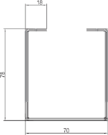
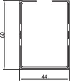
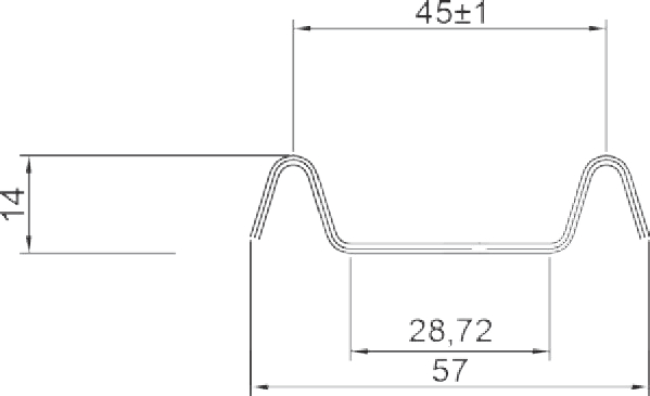
Section
Approve internal/external dimensions, returns, angles, bend radii, thickness and the faces used for holes.
Connection
Use actual brackets, fasteners and the specified coating to check mating fit.
Special interfaces
Define end, corner, raked and gate features by part code and revision.
Define the dimension and interface record
Assign each channel section to the intended part and machine path. Each drawing describes one geometry, not an automatic size range. On the W drawing, 45 ± 1 applies to the marked peak spacing; it is not a general machine accuracy value. Define every other datum and acceptance limit independently, including coated fit and special interfaces. Tighter interface limits affect tooling, gauges and trial scope; similar outlines can still interfere at a return or lose clearance after coating.
Choose your Palisade equipment
Use shortage, rework and work-in-progress records to decide which process to add.
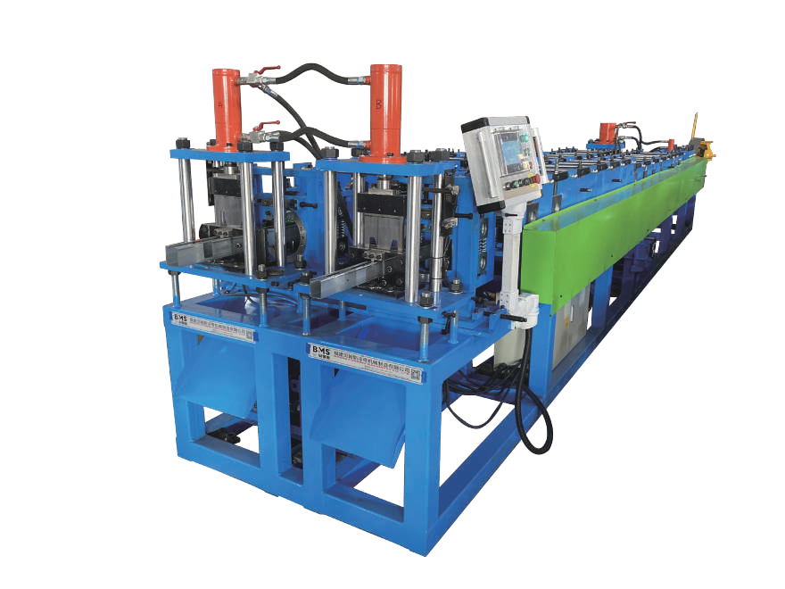
Twin Rail & Post Roll Forming Machine
Bring approved rail and post sections in-house when channel-component supply holds up orders. Define each forming path, tool set and required operating mode.
View Rail & Post Equipment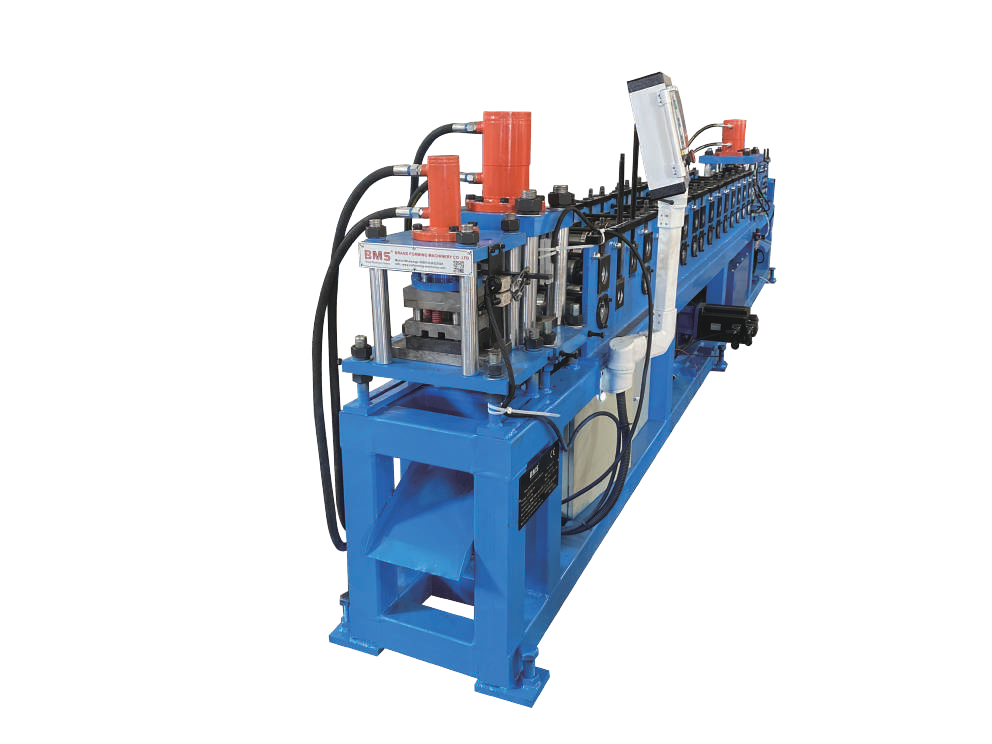
W-Profile Pale Roll Forming Machine
Add W-pale forming when rails and posts are already available. Define the W section, finished length, notch and head-processing tasks as one component specification.
View W-Pale EquipmentChoose the investment boundary
Fill a recurring component shortage
Add a pale task when purchased rails/posts are dependable, or assess rail/post forming against an identified channel-component shortage. Compare the accepted parts with the rest of the order demand.
Trade-off: the smaller machine scope retains purchasing and transfer interfaces.
Bring a stable family in-house first
Retain capable finishing and assembly stations while adding the component task. Set batch identity and buffer arrangements before the next investment.
Trade-off: staged capital spending adds stock and inter-station coordination.
Balance the complete order
Coordinate rails, posts and pales against one BOM and order mix. Include feature processing, hardware, finishing, assembly and packing in the capacity review.
Trade-off: extra forming speed helps only while downstream processes can receive the parts.
Compare the complete supply boundary
A fence manufacturing machine proposal should identify coil handling, slitting or leveling where needed, forming, hole/slot and end operations, cutting, receiving and any straightening. Assign each to the quoted equipment, an option, retained plant, purchasing or subcontracting.
Include finishing, assembly, part identification and packing. List the tools, peripherals, utilities, installation, training, service and acceptance responsibilities in the same scope schedule. Compare the routes against actual shortages and work-in-progress, rather than the longest equipment list.
Define a material window for each task
The rail/post configuration shown uses galvanized steel at 1.8–2.5 mm. Approve the W-pale material and tooling combination separately.
Grade, yield/tensile strength, elongation, base metal thickness (BMT), total coated thickness (TCT), their tolerances and coating.
Width, camber, burr direction, shape, surface, mass and inside/outside diameter.
Link material certificates and coil identity to settings, first-piece checks and released batches. Trial the difficult intended combinations, not only a middle specification.
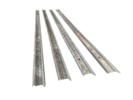
Evaluate thickness, strength and geometry together
A change in grade, thickness, radius or section can change springback and cutting load, with consequences for settings and tools. A thickness window does not approve every steel/coating/section combination within it.
Use separate material schedules for rail/post and W-pale tasks. Record incoming strip condition and the resulting dimensions so operators can distinguish coil variation from a setting or tooling problem after a coil change.
Twin rail & post forming
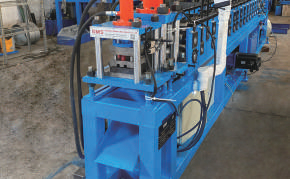
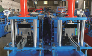
The twin rail/post arrangement has two forming paths and post cutting. Feeding, drive, control, measurement, cutting and take-off determine the useful operating mode.
| Forming stations | 14 × 2 |
|---|---|
| Forming speed | 10–15 m/min |
| Cutting blade material | Cr12 |
Prove the selected path
Assign its profile, material and tools. Demonstrate feed, measurement, cutting and discharge for the required SKU, including stop/restart and the accepted part count.
Prove how the paths interact
Map shared or independent feed, drive, controls, cutting and take-off. Record both accepted counts and the effect of a coil change, stop or fault on the other path.
Read 14 × 2 as two 14-station forming sequences. The 10–15 m/min value describes forming speed; compare accepted parts at the agreed delivery stage. Cutting, handling, coil changes and shared resources affect net output; two paths alone do not establish twice the production.
Map the functions and trial records
Assign the required profile/SKU to each path. Record coil supply, drive, length measurement, start/stop, cutting, controls and take-off as shared or independent functions in the quoted configuration. Include single-path and proposed concurrent modes in the trial, with separate part counts and interruption logs. Final electrical, drive and utility schedules define the purchased equipment boundary.
Place features where they can be controlled
Choose the processing position from tool access, part support and the finished hole-to-end datum.
Before forming
Flat-strip access is easier; verify movement near bends and its effect on guiding.
After forming
Locate from final geometry; provide access and support against local crushing.
Separate station
Complex or infrequent features add handling, queues and identification.
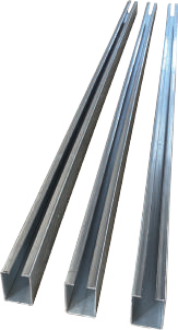
Release features by SKU and finished datum
Define holes, slots, end notches, pitch, length families and head/tail or mirror orientation. Assign each feature to its station and tool, then check first pieces with actual bolts and connection plates. Equal length does not establish identical ends or handing. Identify these variants at release and include the separate-station queue in the order schedule. Post cutting defines a cut-after-forming route; it does not establish an included online hole family or feature tolerance.
W-profile pale production
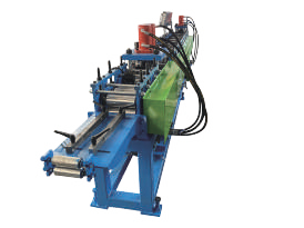
The W-pale route comprises feeding, forming and post cutting. Add the required end-processing tasks from the finished part drawing.
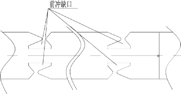
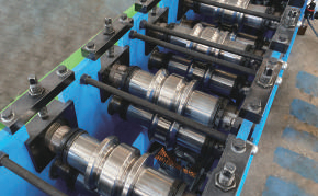
Define each finished feature
The W-pale task forms individual long components. Allocate the section, notch, holes, head and cut length to their required tools and stations.
The sketch identifies pre-punch notching. A new D section or W family changes forming geometry. Pointed, round, multi-point or expanded heads can require different dies and end-processing stations; their inclusion follows the agreed tool schedule.
Define the cut-length datum through the chosen sequence. Check first/last pieces, burrs and head geometry, with tool clearance, scrap removal and long-part support. Headed parts must pass through receiving, racks and packing without bending or surface damage.
Separate the changeover tasks
Length, feature tools and a new section require different actions.
Length & pattern
Program entries, guides and stops, followed by first-piece release. A stored recipe does not replace tool positioning or length checks.
Die & section tools
Identify which dies, blades, guides and rolls are adjusted, exchanged or retained.
New geometry or steel
Reassess forming, springback, cutting and tool reuse for the combination.
Trial A → B → A from the last accepted A to the first released B and the restored A. Record labor, tools, scrap, settings, measurements and release time.
Record the complete A → B → A change
Distinguish program entries from mechanical adjustment and exchanged tools. Use a compatibility matrix for tool reuse, including boundary materials. Track the last good A, first released B and restored A with elapsed time, settings, labor, scrap, measurements and acceptance. Match order frequency and the release endpoint when comparing schedules.
Turn good parts into complete orders
Count every component and item of hardware over one time window and at one delivery stage.
K = minᵢ ⌊Gᵢ / qᵢ⌋
For one repeated kit, each required qᵢ is positive. Gᵢ is released inventory at the agreed stage, with opening stock and rework release defined.
For shared posts and mixed orders, allocate stock once against the full-run BOM. Track shortages, surplus and the process holding delivery.
Allocate the complete run and identify the shortage
For the repeated-kit calculation, the limiting required item sets K. Bare pieces and coated, feature-complete pieces are different inventories. Include reworked parts only after release at the chosen delivery stage.
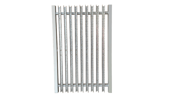
Shared intermediate posts and different end, corner, raked or gate interfaces require the full installation-order BOM. Do not assume two posts for every bay or commit the same part to two orders. Hole/end processing, coating, hardware receipt, assembly and packing can each hold delivery.
Meter speeds and unlike component counts cannot be added to establish complete bays or installed fence length. Compare accepted parts and completed handovers under the same order conditions.
Choose the finish and release condition
The coating route changes processing, lead time and the condition in which fit must be checked.
Manage the coil surface and processed edges
Control forming contact and the incoming coated surface. Cutting and punching introduce edges whose treatment and acceptance follow the product specification.
Release geometry and fit after treatment
Include the galvanizer’s preparation, handling, coating thickness and inspection requirements. Check the resulting shape and connection fit after galvanizing, with its subcontracting cycle in the order schedule.
Carry appearance through the remaining transfers
Specify pretreatment, coating, appearance limits and handling protection. Check coated interfaces using the actual parts and hardware before final release.
Carry fit, identity and protection through packing
Check coated connections with actual parts and hardware. Use agreed coating criteria and samples for roll marks, burrs, color and gloss. Coating thickness affects connection clearance and must be included in the fit check. Welded bays require fixtures, a weld sequence and free-state measurement after unclamping. Preserve part/revision, orientation, finish and batch identity; protect heads and contact surfaces during kit or bay handling.
Check parts across production batches
Prove individual conformity and assembly fit across released batches.
Geometry & features
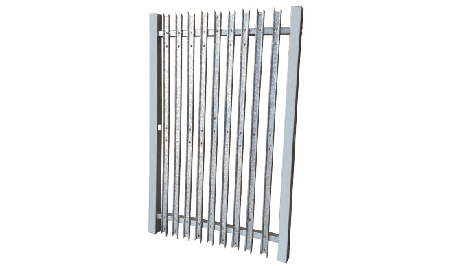
Set datums, limits and gauges for sections, returns, angles, length, straightness, twist, hole pitch, hole-to-end distance, heads, burrs and surfaces. Measure long parts in their agreed free state.
Cross-batch assembly
Mix parts from different paths, coil lots and changeovers with actual hardware and the specified finish.
Release
Investigate forced fit, enlarged holes or unapproved grinding through nonconformance and retest.
Define sampling and the batch release record
Use first-piece, in-process and last-piece checks with agreed sampling and limits. Record component identities and representative special interfaces. A selected matched bay from one batch does not demonstrate interchangeability. Tighter requirements can change tools, support and measurement cost. Keep part, coating and fence-system approvals distinct.
Factory and site acceptance
Agree the inputs, conditions, records and acceptance criteria before the trial.
Factory acceptance · FAT
Freeze CAD, material, tools and configuration. Test required twin modes, continuous batches, coil head/tail conditions, difficult features, first/last pieces and A → B → A recovery.
Site acceptance · SAT
Restore the accepted scope with local utilities, intended coils, trained operators and the actual receiving arrangement.
Release
Record accepted parts, scrap, stops, rework and assembly results. Assign exceptions, retests and remaining-item closure.
Agree the trial schedule and release criteria
Define material quantity, test duration, sampling, tolerances, gauges, assembly scope and signatures before the trial. Assign coil/hardware supply, measuring and signature responsibility. Check holes, ends, free shape, surfaces and the specified assembly with agreed gauges. An empty running demonstration or a selected good piece cannot replace the agreed trial conditions. Record exceptions, corrections, retests and remaining-item owners; machine acceptance and whole-plant production release have separate boundaries.
Prepare the plant and operator handover
Plan coil lifting and supply to each path, receiving supports, racks, buffers, measurement space, tool changes and maintenance access around the purchased scope.
Repeat the accepted setup
Control settings, path/recipe permissions, tool identity, wear checks and backups. Match foundations, electrical and hydraulic services, lifting and auxiliary loads to the final equipment schedule and the actual building and power supply.
Choose critical spares from replacement lead time and the missing parts they create. Demonstrate tool replacement and recovery to an accepted first piece.
Set the handover and service scope
Include operating/maintenance instructions, drawings, accepted mechanical settings and control backups, spare/tool lists, practical operator training and recovery records. Long rails, posts and headed pales need support during transfer to the next station. Assign installation, training and service responsibilities in the purchase scope.
Build a comparable engineering RFQ
Send representative drawings, material, an order BOM and the current bottleneck.
Send the production definition
- Parts & fit. Component, assembly and special-interface CAD, with part codes and revisions.
- Features. Hole, slot, head, handing and length schedules; critical tolerances, gauges and surfaces.
- Steel & coils. Certificates, BMT/TCT, coating and coil dimensions for each task.
- Orders. Quantities, net delivery stage, shortage and rework records.
- Plant. Retained processes, layout, utilities and handling resources.
Define the approval responsibilities
The equipment specification covers tools, peripherals, operating modes, accepted-output conditions and FAT/SAT. The fence designer/project team approves use, post spacing, connections, foundations, loads, installation and required system evidence.
Steel palisade security fencing is a system application; component-machine acceptance alone establishes no fence safety or security rating.
Identify the destination and proposal responsibilities
For the United States, Saudi Arabia, Russia, India or Mexico, identify destination, site use and required technical documents at the RFQ stage. Request a proposal with covered/excluded tasks, individual tools, retained external processes and material, trial, installation, training and service responsibilities.
Palisade production questions
Can we produce W-pales while buying rails and posts?
Yes. Define the purchased rails, brackets and hardware as mating components, then assess the W-pale section and features against those interfaces. Keep incoming-part checks, finishing and kit allocation in the production plan.
Can both twin paths make parts at the same time?
The two-path arrangement alone does not establish the concurrent mode. Specify the required profiles and map shared or independent feeding, drive, controls, cutting and take-off. Trial that mode and record accepted counts separately, including the effect of a stop on the other path.
Does changing a length mean changing the forming tools?
A length change can involve settings while the same approved section remains in use. A new head, hole family, return or section can require dies, guides or roll tools. Record the actual actions and first-piece release in an A-to-B-to-A trial.
Why can individually accepted parts still be difficult to assemble?
Fit depends on several dimensions and the finished coating together. Check the mating hardware and cross-assemble parts from different paths, coil lots and changeovers. Measure free shape and investigate unapproved pulling, drilling or grinding.
How should shared posts be counted for kits?
Use the complete run or installation-order BOM, including end, corner and gate parts. Allocate each available SKU only once. The repeated-kit formula is suitable only when every required quantity is positive and inventory is counted at the same delivery stage.
Should a trial include our own coil and coated assembly?
Use representative intended materials and agree difficult boundary combinations. Include coated assembly when the purchased acceptance scope requires that interface. Define who supplies material, hardware and finishing, and which records establish the accepted result.
What should we send if production CAD is not ready?
Start with clear section and assembly sketches, representative samples, key dimensions, material details and an order BOM. These support the first manufacturing discussion. Freeze controlled component and interface drawings before approving tooling and trial criteria.
What belongs in operator and maintenance handover?
Include controlled settings, tool identification, wear checks, backups, drawings and manuals, critical spares and practical recovery training. Define installation, training and service responsibilities in the equipment scope and demonstrate restoration to an accepted first piece.
Bring your Palisade components into production
Send your profiles, connection details and order BOM. Add the material, finishing route and the component or process currently holding up delivery.