For a floor deck roll forming machine, shortlist fixed stations for a dominant proven profile, removable rafts for several agreed profiles, or double-layer equipment for two recurring profiles.
Choose against your drawings, coil supply and order mix. A four-profile offer does not automatically cover a fifth; two forming levels do not establish simultaneous production.
Compare fixed, rafted and double-layer equipment
Compare where the tooling stays and what must change. The layout name alone does not establish which deck drawings your equipment can produce.
- Fixed stations: Matched forming rolls stay installed. A different geometry may need an engineered adjustment or individual retooling.
- Removable rafts: Stands, shafts and tooling move as assembled modules. Identify any guides, cutters or other parts that stay outside those modules.
- Double-layer: Two forming sets stay installed at different levels. Ask how the required level is selected and which equipment it shares.
Read across each row to compare the three options. On a narrow screen, scroll horizontally through this matrix.
Fixed, rafted and double-layer equipment: compare the same seven requirements
Read the BMS examples as defined profile sets
BMS describes a double-layer floor deck roll forming machine for two distinct profiles. Compare those two drawings with the recurring work you need to supply.

Two forming levels on a BMS double-layer floor-deck machine.
- Four-profile rafted example: BMS describes removable tooling assemblies for four profiles. Match your drawings to the offered tooling; unrelated profiles need separate confirmation.
- Two-profile layer example: Ask which infeed, drives, controls, cutters and discharge equipment are shared.
Check what would change your shortlist
- A dominant long-run profile: Keep fixed stations on the shortlist when alternative orders can be grouped, made elsewhere or served by an agreed retooling arrangement.
- Overlapping delivery peaks: Compare required production windows with available hours. A machine can cover both shapes yet lack time for their combined orders.
- Parallel output required: Request an engineered layout showing the separate coil supply, cutting and unloading arrangements. Do not infer that capability from the number of levels.
- Unused flexibility: Account for the additional tooling, storage and maintenance requirements. Compare them with your current order book before expanding the equipment scope.
Define your deck-profile family and coil supply
Define the family from every drawing and valid material combination. Similar overall dimensions can hide different ribs, side laps or embossing.
Specify the finished deck
- Cross-section: Provide rib height, pitch, cover width, bends and side laps. Mark the drawing revision and the dimensions your customer will inspect.
- Surface and secondary features: Specify embossing pattern and position, plus holes, slots or edge details. Ask which features need different tools or settings.
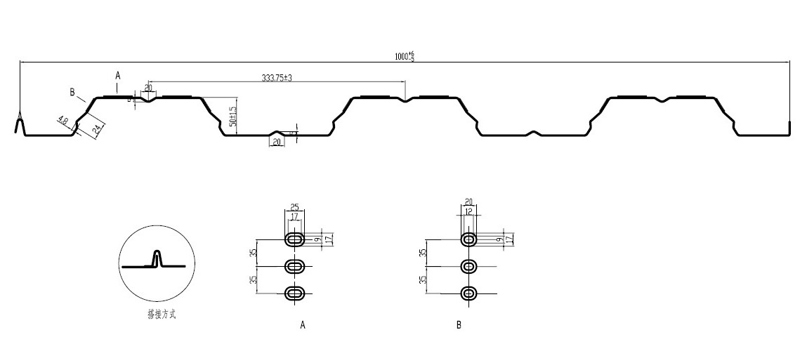
Deck cross-section and embossing details from BMS’s YX50-333-1000 equipment documentation.
BMS’s European-design floor decking machine is described around YX50-333-1000. Use that drawing-level specificity when requesting your own profile family.
State the material, coil and order limits
Inputs that define the proposed equipment range
Separate feed width from cover width
Two widths with different jobs
- Width variation: Ask whether it needs guide adjustment, changed tooling or another forming set. A common coil width does not make finished geometries interchangeable.
- Drawing assignment: Ask for the forming set, usable material combinations, adjustments and excluded features for every drawing.
- Future profiles: Treat a new rib height, lap or embossing pattern as a separate engineering request until compatibility and supplied parts are agreed.
Compare the complete profile-change package. Identify what moves with the tooling, what stays installed and what must be changed separately.
- On the raft: Identify the supplied stands, shafts, rolls and embossing tools for each profile.
- At the base: Ask how the raft is located, fastened and connected to the drive. Request the supplier’s exchange and handling arrangement.
- Between forming levels: Ask how the strip is aligned with the selected tooling and how the output reaches the cutting and discharge equipment.
- Outside the forming set: Include changes to entry guides, levelling, punching and embossing settings. Count their setup work even when the rolls remain assembled.
Match the cutters and exit equipment
BMS’s rafted floor decking rollformer with flying shear lists a front plain shear, servo-controlled flying post-cutoff and automatic stacker.
Its conventional European-design example lists stopped hydraulic post-cutting and unpowered exit racks. Compare these packages as well as the forming rolls.

BMS rafted floor-deck equipment with its sheet exit area.
Cutting and handling checks for each profile
Make scope and price comparable
- Extra rafts: Ask whether the price includes cutting dies, storage stands and exchange equipment.
- Quotation lines: Itemize the decoiler or coil car, guards, controls, exit racks or stacker, with quantities, assigned profiles and optional-item prices.
- Like-for-like price: Compare complete family packages. Identify items supplied locally before treating a lower base-machine price as a lower total purchase cost.
Agree exchange safety requirements
Ask the supplier and your plant safety team to define guarding, the tooling-exchange method and control of electrical, hydraulic and stored energy.
- ISO 12100: Addresses machinery risk assessment. It does not establish conformity of the offered machine.
- ISO 14118: Addresses prevention of unexpected start-up. Ask how the requirements apply to the proposed equipment and exchange arrangement.
Measure changeover against your order mix
Compare complete changeover time using the same start, finish and acceptance conditions. Timing raft movement alone leaves other production losses outside the comparison.
Time the whole switch
A complete changeover interval
Calculate a representative weekly time budget
Use actual metres by profile, batches, due dates, coil changes and available shifts. Apply an accepted running rate for the specified material and length mix.
Illustrative weekly calculation — hypothetical assumptions
- Use demonstrated inputs: The assumed rate and changeover time are not BMS specifications or measured results. Substitute values demonstrated for each proposed configuration.
- Add other stoppages: The example excludes separate coil changes, breaks, maintenance and other losses. Include them without counting the same stopped interval twice.
Check the difficult week
- Urgent batches: Run the comparison for small repeat orders and overlapping delivery peaks, not only average monthly volume.
- Cutting and unloading: Reflect cutter, stacker and manual unloading limits in the accepted running rate or stoppage allowance.
- Comparable offers: Use the same accepted output quantity, profiles, material and length mix in all three calculations.
- People and preparation: Include the operators, handling resources and off-line preparation needed for each change. Check that they are available in the planned shift.
- Order grouping: Grouping the same profile can reduce switching, but changes stock and delivery timing. Check both consequences before changing batch sizes.
Request a profile-specific demonstration and quotation
Request a trial using your drawings and representative coil. Agree the profile transitions, personnel, equipment and acceptance requirements before the demonstration.
Demonstrate a useful profile transition
- Agree the trial matrix. Select profile/material combinations covering the relevant thickness, length and embossing differences. Define dimensions, cut quality and handling requirements with your quality team.
- Run and inspect. Identify the coil grade and thickness. Inspect ribs, cover width, laps, embossing and cut ends against the drawings; check sheet support and stacking.
- Change and restart. Show the actual tooling exchange or level selection, including guides and cutters. Record the complete interval and material used before acceptable output resumes.
- Return to an earlier profile. Where repeat orders matter, compare repeat samples and the work needed to restore the previous setup. A single easy-profile run cannot show that transition.
Send a complete request for quotation (RFQ)
RFQ inputs for your Indian factory
Use the metal deck roll forming machine range to identify candidates. Ask each supplier to quote against the same drawings, production task and supplied equipment.
Request comparable quotation documents
- Profile coverage: Request a drawing-by-drawing list assigning every raft, roll set, embossing tool and cutting die.
- Quoted responsibilities: Separate included items, priced options and locally supplied work. Identify any changes required to shared equipment.
- Support terms: Itemize spare tools, installation, training and service so each quotation covers the same purchase task.
Keep the trial results specific
- Traceable conditions: Record the drawing revision, coil material, thickness, operating conditions and measuring points.
- Representative samples: Retain samples or photographs with measurements, as agreed with the supplier. Compare any promised improvement against that stated trial scope.
- Coverage limits: Results for one profile/material combination do not establish performance for every drawing in the family.
Keep machine capability separate from structural approval. Ask your project engineer for the deck design and performance documentation required for your floor system.
Frequently asked questions
Length alone does not change the cross-section. Confirm the controls, cutoff and handling range; very short or long sheets can create limits with the same forming tools.
Can you feed a wider master coil directly?
Only within the agreed feed range. If your supply needs slitting, request that equipment or service separately; do not assume it is included with the deck former.
It can support separate tooling preparation or maintenance, but cannot replace the rest of the line. Ask which base, drive, controls and handling equipment remain shared and which failures still stop production.
Send a complete profile-specific RFQ
Choose the architecture that covers your agreed profile family, complete equipment scope and difficult-week schedule.
Send BMS the drawing, material, coil, order and electrical inputs above. Request a profile-by-profile equipment recommendation and an itemized quotation.

 日本語
 한국어
 ไทย
 繁體中文
 العربية
 فارسی
 Français
 Русский
 Español
 Português
 English
 Deutsch
 italiano
 Nederlands
 Tiếng Việt
 Polski
 Türkçe
 አማርኛ
 ພາສາລາວ
 ភាសាខ្មែរ
 Bahasa Melayu
 ဗမာစာ
 தமிழ்
 Filipino
 Bahasa Indonesia
 magyar
 Română
 Čeština
 Монгол
 қазақ
 Српски
 हिन्दी
 Kiswahili
 Slovenčina
 Slovenščina
 Norsk
 Svenska
 українська
 Ελληνικά
 Suomi
 Հայերեն
 עברית
 Latine
 Dansk
 اردو
 Shqip
 বাংলা
 Hrvatski
 Afrikaans
 Gaeilge
 Eesti keel
 Māori
 සිංහල
 नेपाली
 Oʻzbekcha
 latviešu
 অসমীয়া
 Беларуская мова
 Esperanto
 मराठी
 پښتو


