


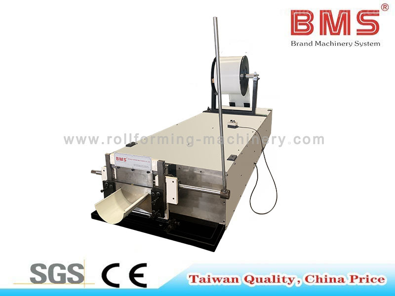
Start with several consecutive formed parts, not a machine adjustment. On a gutter roll forming machine, a scratch that repeats on the same face and in the same feed direction can be investigated by isolating three zones: the coil, the forming rollers and guides, and the runout or stacking equipment. The tests below help maintenance technicians and production supervisors locate the contact point without confusing a coil defect with machine damage.
Use a small, consistent screening sample—commonly three to five parts—for each comparison. This is a practical shop check, not statistical proof or a substitute for the surface-acceptance standard in the product specification.
Key Takeaways
- Establish the pattern first. Record the face, direction, distance from a fixed edge, length and part sequence before changing a setting.
- Test the coil with one controlled change. If the mark disappears after a coil-lot change while settings stay constant, the original coil is a likely contributor; if it remains unchanged, continue downstream.
- Map roller contact instead of guessing. Inspect candidate upper, lower, side or edge-contact components and use a compatible marking material only under an authorized guarded procedure.
- Separate forming from output handling. A mark that disappears with a guarded alternative runout arrangement points to a table, guide, support or stacker contact.
- Treat partial improvement as a multiple-source result. Correct the confirmed contact point, then repeat the comparison rather than declaring the fault solved.
- Close with traceable parts. Compare confirmation parts with the retained baseline samples and record the coil identity, station, action and result.
Establish a Repeatable Baseline
Mark and Measure the Scratch Position
Pull a finished part through the normal inspection process. Under consistent lighting, mark both ends of the scratch with a permanent paint pen or a removable inspection label that will not damage the surface. Use the same fixed edge as the datum on every part. Record the distance from that edge to the scratch, its length, its direction relative to strip travel and whether it is on the top face, bottom face, side wall or cut edge.
Take photographs from the same angle and include the part number in the frame. A steel rule or tape is sufficient for location and length; appearance alone does not establish scratch depth. Keep the baseline parts for direct comparison after each test.
| Record field | How to record it | Why it matters |
|---|---|---|
| Part sequence | Line, date, shift and consecutive part number | Connects the mark to the test run |
| Location | Face plus distance from the same fixed edge, in millimeters | Prevents comparisons from different datums |
| Geometry | Length, direction and approximate width | Helps distinguish a drag line from a short handling scuff |
| Repeat observation | Present or absent on each screened part; note any spacing pattern | Shows whether the condition is stable or intermittent |
| Photo reference | Image number with part and coil identifiers | Makes the observation retrievable later |
Do not apply a universal ±1 mm or ±2 mm acceptance band to every machine. Measurement resolution, flexible profiles and manual marking methods differ. If the plant needs numerical repeatability limits, derive them from the actual measurement method and product requirements. For the initial sort, the useful distinction is whether consecutive parts show the same face, feed direction and edge-referenced region, or whether the marks move randomly.
Rule Out Handling Marks
Inspect the route after the last forming stand before opening the machine. With equipment stopped, look for grit, exposed metal, sharp edges and worn pads at every place where a finished part is lifted, transferred, stacked or bundled. Jewelry and contaminated gloves can also damage a surface; follow site PPE rules rather than removing required protection for a test.
| Handling point | What to inspect | Controlled comparison |
|---|---|---|
| Operator contact | Glove condition and compliance with site rules on rings and watches | Use clean, approved gloves on the same handling route |
| Stacker arms and stops | Burrs, worn pads and exposed fasteners | Compare parts handled before and after the suspect contact |
| Straps and bundling tools | Sharp strap edges and hard contact under tension | Inspect parts before bundling, then after the normal bundle step |
| Racks and transport surfaces | Metal chips, rough welds and unsupported contact points | Place a finished part on a clean, approved support and reinspect |
| Manual transfer | Dragging, part-to-part rubbing and contact with the floor | With the line stopped, carry finished parts through the normal path and compare them with untouched parts |
Handling marks often vary in position or direction because the contact changes between lifts. That is a clue, not a universal rule. A recurring machine-contact mark can also be intermittent, so retain the samples and use the zone tests below when the result is unclear.
Test the Coil Before Adjusting the Machine
Inspect Handling Contacts, Edges and Wraps
Start with the highest-risk contact points: lifting forks, C-hooks, coil grabs, protective sleeves and edge supports. Exposed metal or a damaged pad requires correction before that contact is used again. Then inspect packaging for transport damage and examine the accessible strip surface and both edges under the lighting specified by the plant's receiving procedure.
| Priority | Inspection | Decision and record |
|---|---|---|
| 1 | Lifting and support contacts | Isolate damaged pads or exposed metal; photograph the contact and coil identity |
| 2 | Packaging, straps and separators | Record impact or abrasion locations before discarding packaging |
| 3 | Exposed outer wraps and strip edges | Map scuffs, burrs, cracks and edge damage relative to the strip edge |
| 4 | Inner wraps when the outer inspection or production pattern indicates hidden damage | Use the approved unpacking method and record how far the observed condition continues |
A fixed number of outer or inner wraps cannot prove that a coil is defect-free. Inspect enough of the permitted exposed material to establish whether the condition continues, without loosening a restrained coil or creating a handling hazard. For supplier claims, record the coil and heat numbers, supplier, defect position along the accessible strip, photographs and the packaging condition.
Keep the coating identity in the same record. Galvanized, aluminum-zinc-coated and prepainted surfaces can make similar contact damage look different, but visibility is not a measure of coating loss or corrosion performance. Use the coil supplier's coating-specific acceptance and cleaning instructions; do not assume that one visual severity grade fits every material.
Run a Controlled Coil Swap
Select a replacement coil from a different lot while keeping the specified material, coating, thickness and width suitable for the same job. Record the forming, feeding, speed and cutoff settings before the change. Replace only the coil, then run the same screening sample under the normal guarded production setup and mark the parts with the baseline method.
| Observed result | Interpretation | Next action |
|---|---|---|
| The baseline mark disappears | The original coil is a likely contributor | Preserve both coil identities and samples; inspect the suspect coil and contact the supplier with the record |
| Position, geometry and recurrence are unchanged | The coil is unlikely to be the sole cause | Continue to roller and output-contact tests |
| The mark becomes shorter or less frequent | More than one contact source may be present | Retain the coil result and continue downstream without resetting the evidence |
Do not estimate a universal changeover time or test cost. Record the line's actual lifting resources, downtime and material used so the next investigation can be planned from local data.
Inspect Forming Rollers and Guides
Inspect Surfaces with the Machine Isolated
Use a task light, magnifier, clean lint-free cloth and a cleaner approved for the specific roller surface. Inspect station by station from entry to exit. Look for dents, raised lips, embedded debris, coating pickup, lateral scoring and damaged guide surfaces. Record the station and roll position rather than writing only “roller damaged.”
| Log field | Entries to use |
|---|---|
| Location | Station number; upper, lower, side roll or edge guide; operator or drive side where relevant |
| Observed condition | Dent, raised damage, buildup, scoring, loose component or surface deterioration |
| Part relationship | Matching face and edge-referenced location on the baseline samples |
| Action | Clean, dress, replace or adjust only as permitted by the machine documentation |
| Traceability | Date, technician, photograph and confirmation-part numbers |
Do not use a generic 0.05 mm damage rule or an arbitrary contact-width threshold as the acceptance standard. A useful inspection record states what was observed, where it was found and which product requirement or manufacturer limit controls the decision.
Identify the roller material and finish before cleaning or dressing it. Hard-chrome, ceramic-coated and polyurethane surfaces do not share one repair method. Check the machine documentation, chemical safety data and compatibility instructions; an incompatible solvent or abrasive can damage the roll and create another contact problem. Avoid changing strip tension or roll clearance simply to make a scratch disappear, because those changes can also alter tracking and the formed profile.
Use the machine manual for clearance, bearing-play and alignment tolerances. Entry alignment and roller condition are sensible routine checks, while shaft, bearing and geometry checks belong at the manufacturer-specified interval and after a confirmed contact fault. The original article's generic monthly and quarterly limits should not replace those instructions.
Use Marking Material to Map Contact
Select a layout fluid or marking compound approved for the roller material and the strip coating. Apply it only as the supplier directs; a film that is too thick can smear and obscure the contact pattern. Use the machine's authorized guarded inching or maintenance mode, with personnel clear of nip points. If the line has no safe way to make this observation, stop and arrange qualified service rather than reaching toward a moving roll.
Read the pattern after the test. A wiped region shows contact; a distinct line that aligns with the baseline scratch helps identify the candidate station. A top-face mark directs attention to upper contacts, a bottom-face mark to lower contacts, and side or edge marks to side rolls and guides. These are starting hypotheses, because transferred debris or another downstream contact can produce a similar result.
Repeat count alone does not identify the number of damaged rolls. Repeat spacing depends on effective roll diameter, feed distance, slip, cutoff length and the number of contact points. Under the limited assumption that one roll marks the strip once per revolution without slip, the spacing along the strip would be approximately π × effective roll diameter. Use that calculation only as a screening comparison and verify the actual feed conditions.
After cleaning, dressing or replacing the confirmed component according to its documented procedure, run the same screening sample and compare it with the retained baseline parts. If the line remains, repeat the contact mapping before making another adjustment.
Check Runout and Stacking Contacts
Inspect Every Surface After the Last Forming Stand
With the relevant equipment isolated, examine output rollers, side guides, transition plates, supports, stops, stacker pads, suction cups, clamps, conveyor joints and bundling contacts. Look for embedded grit, worn coverings, rough edges and loose fasteners. Compare the contact bands on these parts with the scratch location on the panel.
| Component | Inspection focus | Record |
|---|---|---|
| Output rollers and bearings | Surface damage, buildup and abnormal rotation under an approved isolated check | Position and observed resistance or damage |
| Guides and transition supports | Contact edges, wear grooves and panel rubbing | Measured condition and matching panel face |
| Stops and stacker contacts | Worn pads, exposed metal and damaged suction cups or clamps | Component identifier and photograph |
| Conveyor and bundling surfaces | Belt joints, chips, strap contacts and part-to-part rubbing | Contact point and when it touches the part |
Use a straightedge, feeler gauge or level only as described in the maintenance procedure, and record actual step, gap and alignment readings. Compare them with the machine builder's tolerances. A universal 0.5 mm height limit or 1 mm guide-gap limit is not defensible across different gutter profiles and lines.
Use a Guarded Alternative Output Test
The purpose of the test is to remove the suspect output contact while leaving the forming settings unchanged. Authorized personnel should select a low-speed, guarded arrangement or install a clean, non-damaging alternative support while the line is isolated. Do not disconnect a drive, remove a support or manually catch panels while the line is operating. High-speed production requires an engineered test method, not improvised hand receiving.
Run the same screening sample and compare position, geometry and recurrence with the normal runout samples. If the mark disappears only under the alternative arrangement, inspect the removed contact path. If it remains unchanged, return to the coil and forming-zone evidence. A shorter or less frequent mark indicates that the output path may be one contributor; correct it and retest before closing the investigation.
Choose the Next Test
- Is there a usable baseline pattern? If not, inspect handling and collect better-controlled samples. If yes, retain the parts and record the coil and settings.
- Does coil inspection or the swap implicate the coil? Correct the coil or handling issue, then repeat the same comparison. If the result is unchanged, keep the settings fixed and move downstream.
- Can a roller or guide contact be matched to the mark? Inspect and map the candidate station, apply one documented correction and retest. Repeat spacing can help, but repeat count alone does not establish how many rolls are damaged.
- Does the mark remain after the forming zone is checked? Compare normal output handling with a guarded alternative arrangement.
- Is the improvement only partial? Keep the confirmed correction, retain both sets of samples and test the remaining zones one change at a time.
This order separates incoming material from machine contact before mechanical adjustments are made. It is not a rule to replace a coil when visible roller damage already explains the mark; use the strongest observed evidence first.
Correct, Verify and Document
Change One Variable and Apply the Product Standard
Make one correction at a time: replace the implicated coil, clean or dress the documented roller, renew a damaged guide pad or correct the confirmed output contact. Keep the other settings stable. Run the same screening sample and compare it directly with the baseline parts.
Close the investigation only when the confirmation parts meet the applicable surface requirement and no unexplained mark remains. Three to five clean parts provide a short-run check, not proof that an intermittent fault will never return. Increase observation when the original problem was intermittent or when the product specification requires a defined inspection plan.
Keep a Traceable Scratch Log
Copy the following fields into the plant's maintenance or quality record. The record should let another technician reproduce the comparison without relying on memory.
| Record group | Required fields |
|---|---|
| Production identity | Date, shift, line, profile, part sequence and machine settings used for the comparison |
| Coil identity | Coil number, heat or lot, supplier, material, coating, thickness and width |
| Scratch evidence | Face, edge-referenced location, length, direction, recurrence and photo numbers |
| Test and correction | Suspected zone, station or component, variable changed, action and technician |
| Confirmation | Confirmation-part numbers, observed result, remaining defect and follow-up owner |
Review accumulated records by station, component and coil lot. Compare counts with how much production each station or lot actually ran; raw counts alone do not establish a defect rate. Keep the baseline and corrected samples with the log until the quality review is complete so an unresolved case can continue from the last confirmed observation.
FAQ
How can scratch depth be measured?
A visual grade or fingernail check does not measure depth. For a nondestructive check, quality personnel can evaluate a calibrated stylus or optical surface-profiling method where access, surface reflectivity and an intact adjacent reference surface permit a reliable reading. A conventional coating thickness gauge does not directly measure groove depth. Cross-sectioning followed by microscopy can be appropriate for laboratory analysis, but it destroys the sample and requires a controlled sectioning and measurement procedure.
Can an intermittent scratch still come from the machine?
Yes. Intermittent debris, changing contact, a sticking output roller or a localized coil condition can produce marks on only some parts. Record speed, coil position, station condition and part sequence around each occurrence, then compare the conditions when the mark appears and disappears.
Should production continue after a repeated scratch is confirmed?
Segregate suspect parts from the last acceptable inspection and follow the plant's quality-hold process rather than mixing them into finished stock. Continued production requires authorization under the applicable product-nonconformance process; an immediate stop is necessary when guarding, machine condition or operator safety is affected.
When should troubleshooting stop and qualified service be called?
Stop when the work requires guard or interlock defeat, uncontrolled manual receiving, shaft or bearing disassembly, roll regrinding, alignment beyond the documented adjustment, or diagnosis of abnormal vibration, heat or noise. Also escalate when a confirmed correction does not change the controlled comparison; repeated unverified adjustments can damage the profile and obscure the original evidence.

