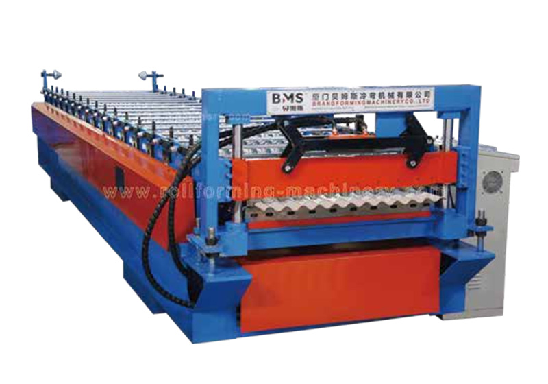
A corrugated sheet making machine for thin-gauge steel needs a specified minimum thickness, controlled strip feeding, suitable roll support and a cutting system matched to your order mix. A high maximum thickness rating tells you little about how well the line handles your thinnest coil.
Start with the galvanized coil you can actually buy. Its thickness variation, strength and coating must match the forming tools and the finished corrugation. Then compare how the proposed line feeds, cuts and supports that material through to the stacked panel.
Define the thin-gauge coil envelope
Specify the lowest and highest actual thickness the line must process, including the tolerance your coil supplier allows. A nominal thickness without its tolerance can leave part of your normal supply outside the agreed machine range.
- Thickness basis. State whether thickness means the steel base or the total coated sheet. BIS guidance for Amendment 2 to IS 277:2018 separates the coating contribution in mechanical-property calculations. Ask your coil supplier to identify the thickness basis on the certificate; use that basis in the equipment enquiry.
- Grade and coating. Pair thickness with the grade certificate, yield-strength range, coating type and coating mass. Thin steel can also be high-strength steel. The tooling must accommodate its forming behaviour, including springback—the tendency to recover after bending. A trial on softer coil does not establish performance on your normal supply.
- Corrugation and feed width. Attach the corrugation drawing. Show pitch, depth, radii, finished width and the overlap detail your customer requires. Ask the tool designer to confirm the corresponding flat feed width. Coil width and finished cover width are different dimensions, so neither a model name nor the decoiler’s maximum width can replace that drawing.
Check the published model against your coil
BMS specifies its YX18-76-760 corrugated sheet machine for galvanized sheet at 0.15–0.25 mm and 500 MPa yield strength. Treat those figures as the published scope of that model. Ask BMS to confirm your actual grade and thickness tolerance; the figures do not describe every corrugated line in its range.
Specify the feed path and forming tools for your thinnest permitted coil. The specification should show how the strip stays supported and aligned from the decoiler to the first forming pass.
Entry and payout: identify each function
- Strip support and guides. Request the entry-table support, adjustable guides and payout control. During starts and stops, the strip should reach the mill without uncontrolled slack or excessive pull.
- Decoiler functions. Do not assume that “hydraulic decoiler” describes every function. Have the supplier distinguish mandrel expansion, coil rotation and braking or loop control.
- Coil fit and threading. Match coil mass, inner diameter and outer diameter to the supplied unit. Ask for a threading demonstration and the guarding and operator procedure that accompany it.
The forming specification should describe repeatable roll-gap adjustment and the pass sequence, not just motor power. BlueScope’s roll-forming bulletin explains why alignment, material properties and springback affect tool design. With thin feed, unwanted squeezing can stretch the strip; poor contact can leave the intended wave underformed.
Use station count in context
BMS lists 24 forming steps for the YX18-76-760. That is a configuration detail, not a universal minimum or a quality score. When comparing a corrugated roll forming machine with fewer or more stations, ask how its tooling develops your specific wave and supports the material between passes.
Require the supplier to demonstrate the agreed thickness and grade combinations. Avoid prescribing a universal roller clearance or tension from a general guide. Those settings belong to the tool design and the material being formed.
Compare cutting and batch change arrangements
Separate cutting the coil at a material change from cutting each finished panel to length. BMS lists a manual pre-cutter for the YX18-76-760, while its production workflow includes hydraulic post-cutting. The upstream manual cutter does not, by itself, mean automatic blank feeding or continuous cutting at full line speed.
Compare your actual batch changes
Give suppliers an actual order mix: panel lengths, pieces per batch, thickness or coating changes, and profile changes. A length change in the controls is different from a coil change or a tooling change. Ask which settings are stored and what requires manual work.
Measure the complete order time
For a useful comparison, time one representative mixed order from its first setup to the final stacked panel. Include threading, coil-end handling, cutting stops and batch changes. A long uninterrupted run can hide the delays that dominate your short orders.
Check output handling and acceptance conditions
Specify discharge support for your longest, thinnest panel. The sheet should reach the stack without dropping, dragging or losing its shape. Agree the equipment layout, operator positions and safe transfer procedures.
- Included equipment. BMS lists an exit rack and describes an automatic stacker as optional for this model. Put your selected arrangement in the quotation.
- Usable panel range. Confirm that the discharge and stacking arrangement accepts your panel lengths, profile and batch sizes, including short runs and bundle changes.
Agree the acceptance sequence
- Identify the trial material. Record the coil certificate, coating and measured thickness. Include the agreed lower and upper thickness limits and relevant grade combinations; label each sample so you can trace it.
- Measure the finished profile and cut. Agree limits for pitch, depth, width, length, squareness, bow and cut-end distortion before the trial. State the measurement tools, support condition and sampling quantity. Check consecutive panels, including after a restart.
- Follow the panel into the stack. Inspect full-length sheets after the proposed transfer and bundling sequence. Record accepted pieces, rejected pieces, elapsed time and reasons for stops during the representative order.
Compare accepted panels per hour, or accepted metres per hour, using the same trial conditions for each proposal. Keep this separate from forming speed. An acceptance plan is a requirement you agree with the supplier; it is not evidence that a particular machine has already passed.
Build the thin-gauge RFQ
Build your request for quotation around the coil, panel and production job. Ask each supplier to mark requirements as included, optional or outside the proposed configuration. This exposes scope differences before you compare prices.
Attach the material and panel documents
- Material certificate. Nominal thickness and tolerance; base or coated thickness basis; grade certificate and strength range; coating type and mass.
- Coil dimensions. Coil width, weight, inner diameter and outer diameter from your actual supply.
- Panel drawing. Corrugation drawing with dimensional tolerances; minimum and maximum panel length.
State the production and factory requirements
- Order mix. Pieces per batch; expected material and profile changes; required accepted output.
- Electrical supply. Your Indian plant’s actual supply voltage, frequency and phase arrangement; available electrical capacity and connection requirements. Request the complete connected-load schedule and cabinet specification. A control-voltage value is not the incoming supply rating.
- Layout and handover. Available floor layout and coil-handling equipment; selected discharge system; operating and setup instructions, guarding, training and spare parts.
- Sample-coil trial. Sample-coil availability, who supplies it, trial quantities and agreed acceptance checks.
If your routine coil supply or product mix extends beyond the proposed envelope, ask for a revised configuration or a clearly separated alternative. Keep that requirement visible in the quotation rather than assuming a thin-gauge model will cover future products.
Request a configuration for your coil and order mix
Choose the line whose feeding, tooling, cutting and discharge arrangement is demonstrated against your coil and order mix. Keep the agreed material limits and sample checks attached to the final equipment specification.
Send BMS your thickness tolerance, grade certificate, coating details, coil width and weight, corrugation drawing, panel lengths and sample-coil availability. Request a proposed thin-gauge configuration and trial plan for your factory.

 日本語
 한국어
 ไทย
 繁體中文
 العربية
 فارسی
 Français
 Русский
 Español
 Português
 English
 Deutsch
 italiano
 Nederlands
 Tiếng Việt
 Polski
 Türkçe
 አማርኛ
 ພາສາລາວ
 ភាសាខ្មែរ
 Bahasa Melayu
 ဗမာစာ
 தமிழ்
 Filipino
 Bahasa Indonesia
 magyar
 Română
 Čeština
 Монгол
 қазақ
 Српски
 हिन्दी
 Kiswahili
 Slovenčina
 Slovenščina
 Norsk
 Svenska
 українська
 Ελληνικά
 Suomi
 Հայերեն
 עברית
 Latine
 Dansk
 اردو
 Shqip
 বাংলা
 Hrvatski
 Afrikaans
 Gaeilge
 Eesti keel
 Māori
 සිංහල
 नेपाली
 Oʻzbekcha
 latviešu
 অসমীয়া
 Беларуская мова
 Esperanto
 मराठी
 پښتو