


Start with the cable tray standard and application boundary
Confirm whether the product is being designed as a cable tray or cable ladder system before machine requirements are discussed, because IEC 61537:2023 applies to cable tray and cable ladder systems for supporting and accommodating cables and possibly other electrical equipment in electrical or communication installations.
The IEC page identifies IEC 61537:2023 as edition 3.0, published on 2023-01-24, with a stability date of 2028, and states that it cancels and replaces the 2006 second edition.
The Cable Tray Institute codes and standards page identifies NEMA VE 1 as a standard for metal cable tray systems and describes it as covering technical requirements for construction, testing, and performance, including load/span class designations.
For procurement, this means the buyer should name the target market standard, request the current official edition where detailed clauses are needed, and avoid asking a machine supplier to infer compliance requirements from a sample photo alone.
Map the line process before choosing equipment modules
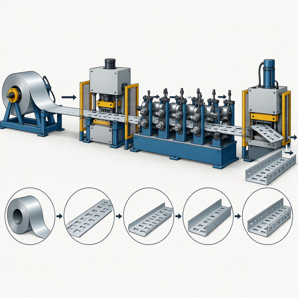
Map the cable tray roll forming line as a sequence from strip handling through forming and length control, because roll forming feeds flat sheet or strip longitudinally through successive paired roller dies that incrementally bend the strip into the final shape.
- Define the incoming strip or coil condition before the forming passes, including the product family, width change needs, and whether flat operations must occur before the profile becomes three-dimensional.
- List the inline operations that belong to the finished tray, such as notching, slotting, punching, embossing, or cutting, because these operations can be combined with contour roll forming.
- Place forming after the operations that need a flat reference surface, unless the drawing or tooling concept requires an operation after partial forming.
- Define cutoff and length handling as part of the process map rather than as an afterthought, because continuous roll forming commonly includes cutting to length.
The result should be a process route, not only a machine title. A clear route helps engineering and purchasing compare whether two proposals are solving the same production problem.
Define punching requirements from the drawing, not from a generic machine name
Define punching by the product drawing and line sequence: roll forming guidance recognizes punching, notching, slotting, and embossing as operations that may be integrated with forming, but it does not make one punching position universal for every tray.
| Requirement to define | Buyer input | How it affects the line discussion |
|---|---|---|
| Hole and slot pattern | Drawing with pattern repeat, edge distances, orientation, and product variants | Determines which flat or partially formed operations must be considered together with punching, notching, and slotting. |
| Punching location | Decision on pre-form, between-stand, or post-form concept for the required geometry | Affects whether punching is treated as an integrated inline operation before or during the roll forming sequence. |
| Variant changeover | List of widths, heights, lengths, and hole patterns that must be produced | Helps the supplier explain tooling change, control recipe, and mechanical adjustment assumptions without relying on a generic line label. |
| Acceptance sample | Marked drawing and finished sample requirements | Gives purchasing a concrete basis for comparing proposal scope, trial criteria, and tooling responsibility. |
Translate tray geometry into forming requirements
Tray geometry must be translated into material, bend, tolerance, and loading inputs because roll-pair count and mill design depend on material grade, finished-part complexity, and equipment design.
| Forming input | What to provide | Why it matters |
|---|---|---|
| Material grade and thickness | Grade range, thickness range, coating condition, and any grade substitution plan | Higher strength and thickness can affect forming forces, shaft loading, horsepower requirement, forming pressure, and bend-radius limits. |
| Profile complexity | Sidewall height, flange or return details, ribs, edge forms, and corner features | Finished-part complexity is one of the drivers that affects the number of roll pairs and mill design. |
| Bend and springback control | Critical angles, radii, straightness, twist limits, and inspection method | Material strength and thickness influence springback and forming pressure, so tolerances should be discussed with the tooling concept. |
| Line loading assumptions | Maximum profile case and the most demanding material case | Forces, shaft loading, horsepower, and pass count are affected by the combination of material and profile requirements. |
Build a requirements checklist for the RFQ
A strong RFQ separates product compliance targets from machine configuration inputs, then gives suppliers the drawings and operating assumptions needed to propose a line responsibly.
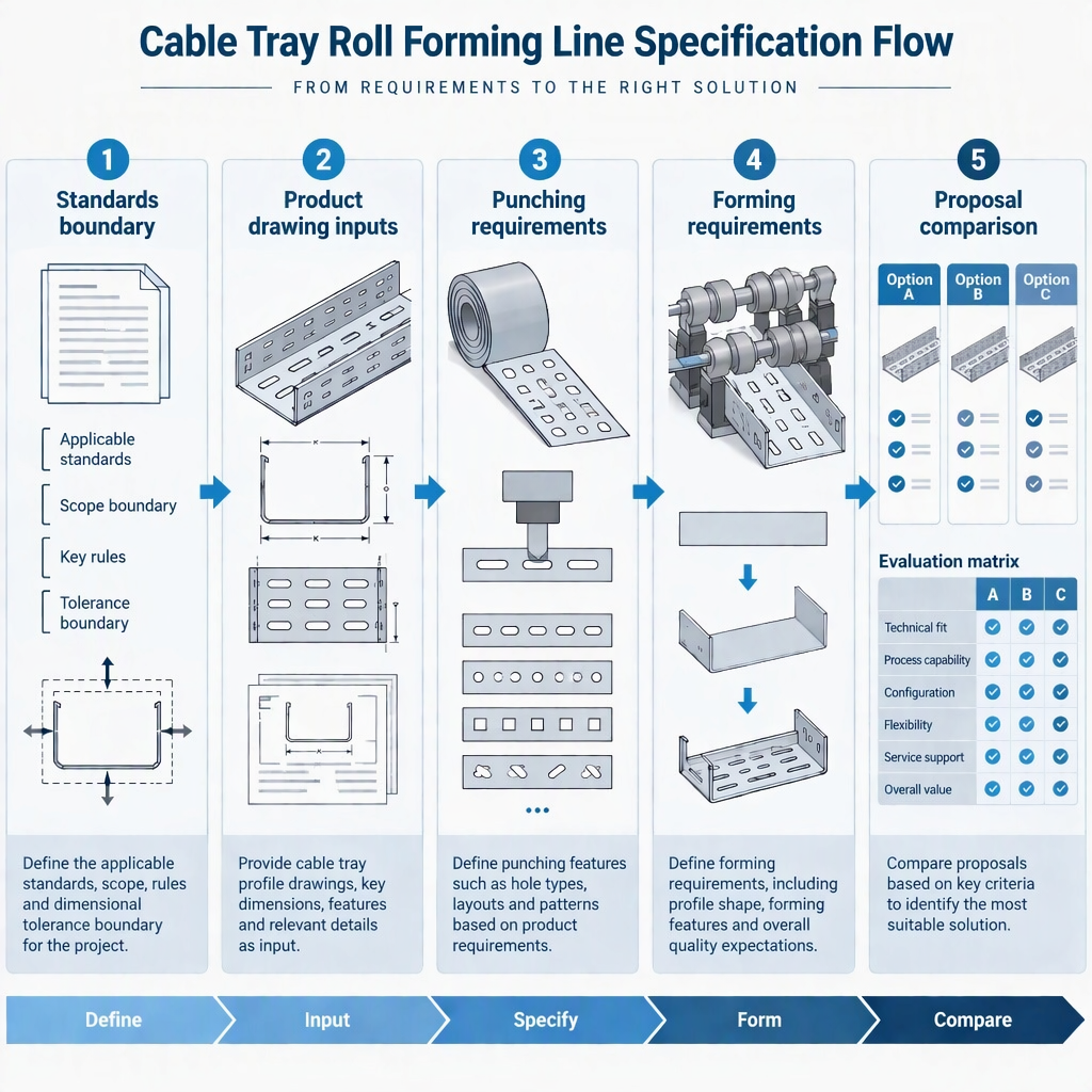
- Name the cable tray or cable ladder standard family and the intended installation market, including whether IEC 61537:2023 is part of the product target.
- If NEMA VE 1 or load/span class designations are relevant, obtain the current official standard text for detailed product and test requirements.
- Attach product drawings for every required width, height, length, sidewall form, flange, return, rib, slot, hole, and end condition.
- Identify which operations must be inline, including punching, notching, slotting, embossing, forming, and cutting to length.
- State material grade, thickness range, bend limits, tolerance targets, and the most demanding profile case for tooling and loading discussion.
- Ask for acceptance criteria: sample dimensions, hole-position checks, profile straightness, changeover demonstration, and documentation to be delivered with the line.
This checklist keeps the RFQ focused on requirements a supplier can design against, rather than on unsourced expectations for speed, tonnage, stand count, or price.
Compare proposals by requirement coverage
Compare proposals by how completely they address material, profile, forming, and loading drivers, not by a headline machine name or an unsupported production-speed claim.
| Comparison field | What a complete proposal should clarify | Buyer check |
|---|---|---|
| Standards boundary | Which cable tray or cable ladder standard target the product is being designed around | Confirm the supplier is not treating equipment capability as the same thing as product certification. |
| Punching concept | Where punching, slotting, notching, or embossing sits in the process route | Match the proposed operation position to the drawing and inspection datum. |
| Forming design basis | Material grade, thickness, profile complexity, springback, force, shaft loading, and pass-count assumptions | Check whether the most demanding profile case is explicitly covered. |
| Changeover and variants | How the proposal handles width, height, length, and pattern changes | Ask for the mechanical and control assumptions, not only the final tray names. |
| Acceptance and documentation | Trial parts, inspection method, drawings, manuals, and training scope stated in the offer | Compare deliverables line by line before commercial negotiation. |
- Reject vague alternatives that do not identify the product family, drawing revision, material case, and punching pattern basis.
- Ask suppliers to separate included modules from optional modules so that pre-punching, post-punching, cutoff, stacking, and controls are not confused.
- Use sample-part approval and documentation deliverables as purchasing gates before final acceptance.
Keep machine capability separate from product compliance
Buying a cable tray roll forming line does not by itself prove that the finished cable tray system complies with IEC 61537:2023, because the IEC standard addresses requirements and tests for cable tray and cable ladder systems, not a universal machine design.
IEC 61537:2023 states the system scope for supporting and accommodating cables and possibly other electrical equipment; that scope helps define the product target but does not replace product testing, documentation, or project approval.
The Cable Tray Institute page places NEMA VE 1 among cable tray standards and describes its construction, testing, performance, and load/span role, which should be handled as product and documentation requirements during procurement.
Use the machine proposal to judge whether the process can make the required profiles and patterns. Use the relevant standards, tests, project specifications, and authority requirements to judge whether the finished cable tray is acceptable for its market.
Conclusion
Before purchase approval, define the product standard target, drawing variants, punching concept, forming drivers, and acceptance checks clearly enough that every supplier is quoting the same cable tray roll forming line requirement.
- Set the cable tray or cable ladder application boundary before machinery selection.
- Treat punching, notching, slotting, forming, and cutting as connected process decisions.
- Base forming discussions on material, thickness, profile complexity, bend behavior, and machine loading.
- Compare proposals by requirement coverage, deliverables, and acceptance criteria rather than by unsupported headline claims.
FAQs about cable tray roll forming line requirements
These questions help purchasing and process teams turn cable tray product intent into a clearer equipment specification.
Which standard should I confirm first?
Confirm whether IEC 61537:2023 applies to the intended cable tray or cable ladder system, then identify any market-specific standards, project specifications, or local rules that also govern the finished product.
Can I use NEMA VE 1 as a machine specification?
Use NEMA VE 1 as a product-standard reference for metal cable tray systems and load/span designations where applicable, but ask for the current official standard text and do not treat a product standard as a complete machine design brief.
Should holes be punched before or after forming?
Decide from the drawing, datum, pattern accuracy, profile shape, and tooling concept; roll forming guidance supports integrating punching, slotting, and notching with forming, but it does not establish one universal location for every tray.
Can a buyer specify the number of roll stands in advance?
A buyer can state constraints and expectations, but the required number of roll pairs depends on material grade, finished-part complexity, and mill design, so the supplier should explain the design basis rather than receive an arbitrary stand count.
What speed or punching tonnage should I ask for?
Ask suppliers to calculate or propose speed and punching capacity from your material, thickness, hole pattern, profile geometry, control concept, and acceptance requirements. Do not use a generic value when the drawing and material case are not fixed.
Does the machine certificate prove cable tray compliance?
No. The finished cable tray or cable ladder system must be judged against the applicable product requirements, tests, documentation, and project rules; machine capability is only one part of making a compliant product.
What documents should be attached to the RFQ?
Attach drawings, material specifications, thickness range, tolerance targets, critical bend details, hole and slot layouts, variant list, inspection plan, and the most demanding profile case so suppliers can address forming pressure, springback, pass count, and machine loading.


