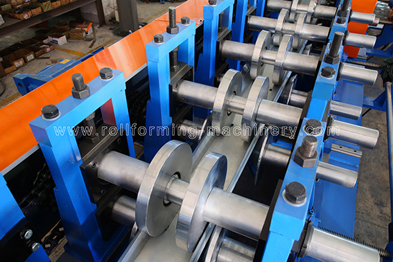
Compare a purlin machine on the hardest jobs you actually plan to run. Give each supplier the same coil limits, developed strip width, profile drawing, hole pattern and finished length. Then compare the drive capacity and accepted output for those conditions. A maximum thickness and a motor rating leave too many of those conditions open.
Forming load. Your thickest, highest-strength part may put the most load on the forming mill.
Punch and cut cadence. A shorter part with more holes can push the punch and cutoff harder.
Long-part handling. A long section can expose twist or handling problems that a short sample hides.
Treat those as separate production jobs when you request a quote and plan the trial.
Define thickness, strength and developed width together
Specify thickness, yield strength and developed width together for each job. A machine’s maximum gauge may apply to a narrower strip or a lower-strength grade than you plan to run. If your thickest and strongest requirements belong to different parts, list those parts as separate jobs in the RFQ. Ask about a combined upper limit only if you need to run that combination.
Start with the coil and the released drawing
Grade and mill data. Request the actual mill certificate and match it to the coil ID. Give the supplier the grade and material specification, coating if applicable, and the permitted yield range in MPa. Include tensile strength and elongation where the material specification and certificate provide them. Yield strength helps you assess forming load and how far the steel may spring back after leaving the rolls. Tensile strength is a separate value and can inform the tooling supplier’s shear estimate.
Thickness and tolerance. Give the nominal thickness and both tolerance endpoints in millimetres. For coated steel, say whether the numbers refer to base metal or total coated thickness. A quote on nominal gauge can miss the thick end of your permitted stock. Record the thickness basis again on the trial sheet so the sample and the purchase specification can be compared.
Developed width and section geometry. Developed width is the width of the flat strip fed into the machine. The web is only one part of the finished section. Two drawings with the same web can have different flange lengths, lips and bend radii, and can need different strip widths and roll setups. Record the approved slit width for each job and send the full drawing so the supplier can check the flat development and the strip width that fits the proposed line.
BMS shows these finished sections alongside the C100-400/Z120-400 listing. Use your own section drawing to identify the web, flanges and return lips and specify the developed strip width.
Read a catalog range as a starting point
For example, BMS lists 0.95–3.0 mm material thickness and 450–550 MPa yield strength for its C100-400/Z120-400 CZ purlin roll forming machine. The listing gives feed width according to the drawings. If you need 3.0 mm at the upper yield value, give BMS the actual strip width and profile and ask whether that combination is covered at your required production rate. The two published ranges alone leave that question open.
Compare forming and drive architecture
Compare the forming mill and the drive at the same job and line speed. The mill has to hold the rolls in position under load. The drive has to turn them and feed the strip for the required run. A line can have enough torque to move the strip and still produce a flange outside tolerance if the roll gap changes under load.
Check how the stands hold and shape the strip
Roll pass sequence. Each roll pair makes part of the bend. A tighter radius, a different flange or higher-strength steel can change how the supplier distributes bending across the passes and compensates for springback. AHSS Insights describes how steel properties and section geometry affect pass requirements. Ask for the proposed pass sequence or a drawing that shows how the section develops. A stand count by itself tells you little about how a given bend is shared across those stands.
Shaft and stand support. Follow the load from the rolls through their shafts, bearings and stands. Shaft or stand deflection can change the roll gap during the run and shift the finished geometry. For a wide strip, confirm where the roll load sits relative to the bearing supports. Compare the shaft span, support arrangement and setup for the actual profile. A larger shaft diameter on a brochure is only one part of that comparison.
Forming rolls, shafts and stands on the BMS CU80–300 example. Ask the supplier how the proposed line supports its rolls under load for your profile.
Compare torque at the same point in the drive
Ask both suppliers to identify where they rate torque in N·m, such as at a gearbox output or a driven roll shaft. A gearbox trades speed for torque, and the gearbox and downstream components have their own limits. A line that drives several stands from one transmission and a line with separate drive groups distribute the load differently. Ask which stands are powered and where the supplier expects the limiting load on your job.
Use the same operating point. Request the available continuous torque at the roll speed that corresponds to your proposed loaded line speed. If one quote gives motor-shaft torque and another gives roll-shaft torque, ask for a comparable basis before judging either figure.
Separate steady running from start and restart. Ask how much short-duration torque is available, for how long, and whether the drive can restart with your strip in the mill where that test is agreed. ABB’s drive dimensioning guide explains why a self-cooled motor may have less continuous torque at low speed. A slow sample run can therefore leave the continuous-duty question open.
Identify the component that sets the limit. Ask for the supplier’s load and rating summary for the motor, drive, transmission and relevant roll shafts. Have them state any conditions on speed, cooling, run duration or setup. Compare the rating with the expected load at the same point in the transmission.
Two offers for the same Z profile
Suppose your RFQ specifies 2.8 mm steel with a trial yield of 520 MPa, 420 mm strip and a Z profile with a fixed hole pattern and finished length. You request 10 m/min under load.
Illustrative comparison at 10 m/min under load
Offer
Quoted basis
Offer A
Lists a higher motor kW and a top speed.
Offer B
Specifies continuous gearbox-output torque at the required roll speed and quotes an accepted parts-per-hour rate with the punch and cutter running.
Which offer moves to trial?
Take Offer B to a loaded trial first. Check its quoted torque and accepted output on that job. These inputs are illustrative and do not describe a rated or tested machine.
Check punching and cutoff capability under the same material
Qualify punching and cutoff with the same grade, thickness and profile you used for the forming comparison. Request a finished-part rate with the production hole program and cutter in use. A coil that passes through the rolls can still require a slower punch sequence, a different cutting die or a longer outfeed.
Check force per stroke and strokes per part
Drawing and hit sequence. Give the supplier the round holes and slots, their locations from the drawing datum, and the required pitch and edge distances. Ask which features are punched together and which need separate hits.
Peak force and repeated strokes. Mate Precision Technologies identifies cut perimeter, sheet thickness and shear strength as inputs to punching force. Several features in one stroke raise the length being sheared at once. Splitting the hits can ease peak force but may add stops or limit the rate.
Finished-hole quality. For holes near a bend, check shape and location on the finished part. Flat-strip punching gives you better access to the blank, but forming can change holes near the bend. Punching after forming needs room for the tool and support for the section. Ask what clearance and tooling the supplier proposes for your material range, and agree how burr, slot shape and positional error will be checked.
Check the cut and the time between cuts
Ask where the cut happens and whether the strip stops.
What each cutoff arrangement changes
Cut location or motion
What to verify at your rate
Location: before forming
Cutting flat strip before forming avoids cutting through the finished section, but the resulting blanks have to feed through the mill.
Location: after forming
Cutting after forming requires tooling that fits and supports the finished section.
Motion: flying cutoff
A flying cutoff travels with the part during the cut. Its return cycle still has to fit between cuts at the intended line speed.
Motion: stop-to-cut
The strip stops for the cut. Include the stop and restart in the finished-part rate.
Check the shortest and longest production parts
Shortest recurring part. Use your shortest recurring part or the tightest repeat pattern to check cycling. Short parts usually call for more cuts per metre.
Long-part support. Long parts test support, clearance and collection.
Cut quality and end flare. Look for cut length, squareness, burr and deformation at both ends. Research by Matthias Moneke and Peter Groche describes how stresses from forming can be released as end flare. Measure the required dimensions near the ends as well as in the middle so you can see where a deviation occurs.
Use the same output basis across quotes
When reviewing quotes, record the forming speed in m/min and the accepted parts per hour for the same length and hole pattern. Ask what happens between coil entry and the count of finished parts, including startup pieces, punch and cut pauses, outfeed delays and rejects. Agree which of those the recorded trial window includes so both suppliers report output on the same basis.
Request an envelope-specific trial
Build your trial around the jobs most likely to uncover different limits. If the thickest, strongest strip is also your widest required strip, test that combination. If the jobs differ, keep them separate. Each job should identify the coil, tooling and drawing that the supplier must use, as well as the result you want recorded.
Application-envelope matrix for your RFQ and trial
Highest forming demand
Field
Specify or request
Grade and strength
Certified grade for the highest forming demand. Record actual yield and tensile values.
Thickness (mm)
Upper permitted value for this job
Developed width (mm)
Approved slit width for this drawing
Profile
C or Z drawing with the critical bend and lip
Punching
Use the drawing pattern
Cutoff and length
Specified cut method and part length
Trial result requested
Sustained loaded speed, drive readings and measured flange, lip and angle
Repeated holes and short cuts
Field
Specify or request
Grade and strength
Certified grade for the repeated-hole job
Thickness (mm)
Actual trial thickness within the approved range
Developed width (mm)
Slit width used for this part
Profile
Drawing with the shortest recurring punched part
Punching
Use the actual pattern and hit sequence
Cutoff and length
Shortest recurring cut length
Trial result requested
Accepted parts per hour, hole size and position, and cut quality
Longest finished purlin
Field
Specify or request
Grade and strength
Certified grade for the longest part
Thickness (mm)
Actual trial thickness within the approved range
Developed width (mm)
Slit width used for this part
Profile
Longest required C or Z part drawing
Punching
Use specified holes, if any
Cutoff and length
Longest length with quoted outfeed support
Trial result requested
Measured length, bow, twist, end condition and handling through discharge
Replace the example entries with your own values. Add a separate case if you expect the minimum thickness to challenge tracking or dimensional control on the quoted setup. Give every job a reference number and drawing revision. If two concerns can be tested on the same job, record both measurements for that job.
Agree how each job will be tested
Agree the test conditions before the run. Set the trial speed or output target, run duration or number of consecutive parts, measurement locations and who witnesses. Use the quoted drive, roll setup, punch tools, cutoff and outfeed, or document each difference from the offered build.
Tie the coil to the result. Supply sample coil with a matching mill certificate and record measured thickness and slit width. If a substitute coil or a lower-strength lot is used, record exactly what it proves. Keep the untested strength or thickness condition open unless you accept a separate engineering basis or arrange a follow-up run.
Record what happens during the run. Log the settings, speeds, accepted pieces, interruptions and rejects. For the drive comparison, agree which data are logged, such as current or drive-reported torque, and their measurement basis. Check parts at agreed intervals during the run so initial setup samples and sustained performance are both visible.
Specify acceptance and exclusions
Write the acceptance criteria into the order before the trial. Tie each required result to a drawing revision, material range and minimum accepted output where applicable. If your requirement is for punched and cut parts, apply the output criterion to those finished parts.
Turn the trial into an acceptance record
Agree how to measure web, flange, lip and angles, as well as bow, twist, hole location and cut length. Use the drawing’s datums and state where readings are taken along the part. Agree the supports used to measure long sections, the measuring equipment and how many parts to inspect. Include finish, burr or end flare where they affect fit or are called out on the drawing.
Assign a decision to each job
Covered. Record the accepted combination, tooling and output basis, and attach the signed measurements or other agreed evidence.
Conditional. Write down the exact condition, such as a lower accepted rate on the widest strip or a trial still due on the higher-yield coil. Assign the action and state when it must be closed.
Excluded. List the unsupported material or profile combinations, hole patterns, lengths or configurations. If an option would bring a case into scope, name it and state how it will be verified.
Confirm the Russian plant handover requirements
Site electrical supply. For a line going to a plant in Russia, request the actual site electrical supply from the plant team, including voltage, frequency and phase. Ask the supplier to confirm the electrical design and connected load against that supply.
Handover documents and languages. Obtain the list of required documents and languages from your project team and importer. Put the agreed manuals, electrical drawings, parts lists, inspection records and any required project-specific conformity documents into the handover schedule.
Checks after installation. Identify the checks to repeat on site once the production line is installed.
Questions about qualifying a purlin former
Can you qualify production coil from a different supplier with the same grade name?
Check the new mill certificate and the agreed incoming limits first. Consider coating, thickness, yield, tensile strength and other properties required by your material specification. If the new coil falls outside your agreed limits or changes a condition critical to the part, agree what must be rechecked before treating the substitution as covered.
Does a short trial establish a daily production rate?
It shows what the line did during the observed window. For a shift estimate, include the expected batch mix, coil and tooling changes, normal interruptions and rejects. Agree a longer run if a sustained production rate is a purchase condition.
Request a review of your production jobs
Shortlist the line that can support the required jobs with an agreed configuration, rate and acceptance method. Resolve any conditional job that matters to your production plan before you rely on it in the purchase order.
Ask BMS for a written application review and proposed trial.
Completed matrix. Send your loaded-speed and accepted-output targets by job.
Material and sample. Include the actual mill certificate, minimum and maximum thickness, yield range and the sample coil you can provide.
Drawings and lengths. Send the full profile drawing and developed strip width, hole details, and your shortest recurring and longest required lengths.
Installation inputs. Include the site electrical supply and the required documents.
Ask BMS to return the proposed setup, expected output basis, trial plan and any exclusions for each job.
Founded in 1992, BMS Machinery joined XIAMEN BMS GROUP in 2017. Our manufacturing network in China includes 8 factories, 6 machining centers and 1 steel structure company, covering over 30,000 m². Supporting credentials include ISO9001:2015 quality management certification and SGS-issued CE/UKCA machinery compliance verifications. XIAMEN BMS GROUP’s Dun & Bradstreet D‑U‑N‑S Number is 55-379-8879.

 日本語
 한국어
 ไทย
 繁體中文
 العربية
 فارسی
 Français
 Русский
 Español
 Português
 English
 Deutsch
 italiano
 Nederlands
 Tiếng Việt
 Polski
 Türkçe
 አማርኛ
 ພາສາລາວ
 ភាសាខ្មែរ
 Bahasa Melayu
 ဗမာစာ
 தமிழ்
 Filipino
 Bahasa Indonesia
 magyar
 Română
 Čeština
 Монгол
 қазақ
 Српски
 हिन्दी
 Kiswahili
 Slovenčina
 Slovenščina
 Norsk
 Svenska
 українська
 Ελληνικά
 Suomi
 Հայերեն
 עברית
 Latine
 Dansk
 اردو
 Shqip
 বাংলা
 Hrvatski
 Afrikaans
 Gaeilge
 Eesti keel
 Māori
 සිංහල
 नेपाली
 Oʻzbekcha
 latviešu
 অসমীয়া
 Беларуская мова
 Esperanto
 मराठी
 پښتو