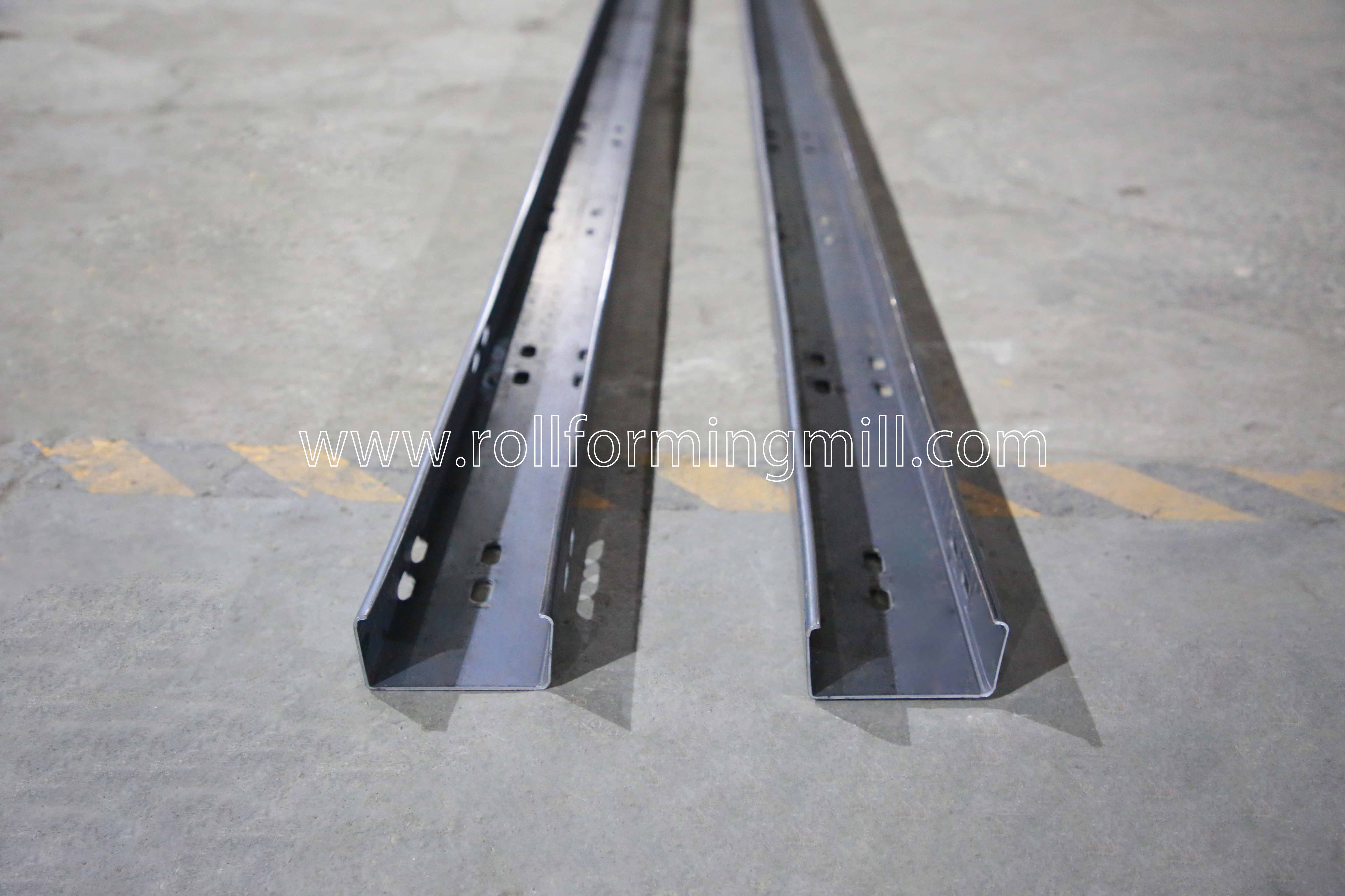
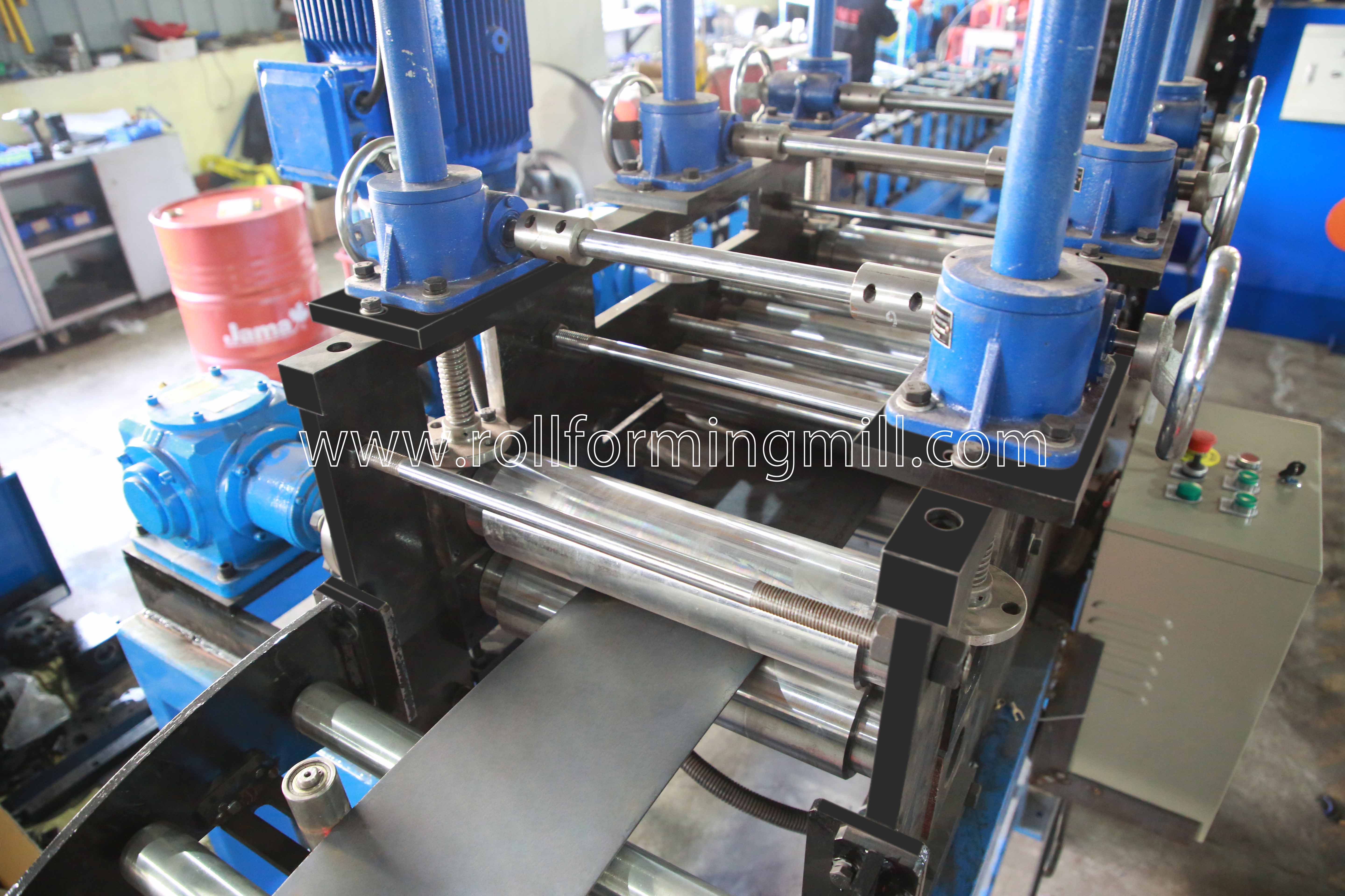
Build your solar purlin roll forming machine quotation around the steel C-support parts you plan to make. For each drawing revision, list the coil specifications, hole patterns and cut lengths you need to run. Ask the supplier to confirm which combinations the line will run.
Define the C-support profile family
BMS lists a 40–160 mm web range for the C40-160. The web is the broad face joining the two flanges. You can use that range to screen steel mounting members, then confirm the full geometry of each part on its drawing.
Web and dimensions. Mark exactly where you measure the web. Specify whether you use inside or outside dimensions and ask the bidder to use the same convention.
Flanges, lips and bends. Dimension both flanges, return lips, inside radii, angles and steel thickness. Show the mating bracket face and the tolerances that affect fit.
Drawing variants. Give each part its own number and revision. Identify left- and right-hand parts and list every required size combination.
What changes when the web stays the same?
A wider flange or longer lip can require a different slit width at the same web size. Ask for the developed strip width, the flat width before bending, for each section.
Shared rolls. Ask which drawings one roll set can cover through adjustment and which require extra tooling.
Range checks. Use your narrowest and widest ordered webs, then check any intermediate section with a different flange, lip or bend radius.
Match coil strength and thickness to the model
BMS lists galvanised steel (GI) or cold-rolled steel (CRC) at 2.0–4.0 mm for the C40-160, with 22 forming steps. Use those figures to screen the material and model. For each drawing, ask the bidder to confirm the grade and thickness together, especially for your thickest, strongest or tightest-radius jobs.
Why the same thickness can behave differently
WorldAutoSteel’s roll forming guidance ties the behaviour of the strip to its mechanical properties. A different coil at the same nominal thickness can change both the flange angle and the punching setup.
Forming load and springback. The rolls bend the strip in stages. A change in steel strength can change the forming load and how far the flange springs back as it leaves the rolls.
Punching force. Tensile strength also affects the force needed to punch a hole.
What to send with the material certificate
Grade and properties. Send the certificate and purchase specification for the actual coil. Give the grade, yield and tensile strength in MPa, and elongation.
Thickness and coating. Give the thickness range and any coating designation. Specify whether thickness refers to base steel or coated strip.
Coil dimensions and supply. List available slit widths and tolerances, coil mass, and inside and outside diameters. Tell the bidder who slits the coil and flag supplier limits on camber, the sideways curve along a strip edge.
If the builder proposes a narrower strength or thickness range for a particular drawing, have it show that limit against the relevant part number. You can then decide whether to change your coil purchase or quote a different configuration for that job.
Specify punching and cut-length requirements
Dimension each hole and slot on the finished C section. Use the cut end and a named edge or face as reference points.
Face and position. Name the web or exact flange for each row. Give the transverse offset and the permitted position error.
Feature shape. Show hole diameter or slot length, width and direction. Identify mirrored layouts separately.
Position along the length. Give the centre-to-centre pitch and the first and last offsets from the cut ends.
BMS product example showing apertures on the web and flanges. Mark the required faces and offsets on your own drawing.
BMS describes hydraulic punching before forming and servo-controlled cutoff after forming. The supplier has to place each feature on the flat strip so it lands in the correct position on the finished web or flange.
Near a bend. Ask how the supplier will check the slot’s shape and position after forming.
Punch tooling. Ask the supplier to name the included dies in its offer and identify each row that needs another tool or a separate operation.
Check whether the pattern fits each cut length
In this hypothetical example, five hole centres start 50 mm from the first end at a pitch of 200 mm. The last centre is 50 + (4 × 200) = 850 mm from the first end.
Far-end offset at the same hole pitch
Cut length
Last hole centre
Far-end offset
900 mm
850 mm
50 mm
1,000 mm
850 mm
150 mm
A correct cut length and repeat pitch can still leave the last hole out of position. If both lengths require 50 mm at each end, have your design team approve another pattern rule for the longer part. Then ask the supplier to quote the program and tooling for the approved spacing or end feature.
Agree what to measure after cutoff
Cutoff and ends. Ask for the cutoff tool, usable lengths and limits for burrs and end distortion.
Finished part. At the trial, measure overall length and both end offsets against their individual drawing limits. Check the fit of the actual fastener or bracket.
Compare feeding and output-handling scope
Compare what the line takes in and what your team can remove from it. BMS shows its solar purlin roll forming machine with a hydraulic decoiler, feeding and levelling equipment, and an exit rack. Use that layout as a starting point for the equipment list in your bid.
The BMS feed and levelling unit receives flat slit strip. Check which loading equipment and upstream work your quote includes.
Coil entry. Quote against the actual slit-coil width, mass and diameter range. If you slit parent coils, say where that operation ends and how finished-width coil reaches the line. Identify who supplies the loading equipment and where it sits.
Finished-part exit. Give bidders your shortest and longest finished lengths. Specify how short parts land and how long parts stay supported during transfer. Assign part removal, counting and packing. Compare a rack and powered handling on the same batch basis.
Plant and utilities. Give your actual voltage, phase, frequency, available electrical capacity and connection constraints. Ask for infeed and discharge clearances and a full electrical load schedule, including supplied coil-handling and receiving equipment.
Time the change between two jobs
Start with the last accepted part. Select two jobs that follow each other regularly. Start timing after the last part of the outgoing job passes inspection.
Record what changes. Log powered roll adjustments and any manual guide settings, coil, punch die or cutoff tool changes, and program selection.
Stop at the first accepted part. Include inspection and stop timing when the first part of the incoming job passes.
Assemble a drawing-based RFQ
Give each drawing revision, coil specification, hole pattern and finished-length combination a job reference in your request for quotation (RFQ). Add the quantity per batch and the expected run order. Have each bidder use the same references in its reply.
Quotation matrix for your C-profile production line
What to compare
Drawing inputs and supplier reply
Size range
Your input — Section drawings with revisions, web, flanges, lips, radii and tolerances
Supplier reply — Jobs covered by the offered range, exceptions and any required tooling or adjustments
Material
Your input — Certificate, grade, thickness range, coating and slit-coil data
Supplier reply — The approved material and strip width for each drawing, with any restrictions
Hole patterns
Your input — Web and flange drawings, datums, pitch, slots and end offsets
Supplier reply — Included dies, supported patterns, any secondary work and finished-part checks
Changeover
Your input — Two named jobs and their place in the batch schedule
Supplier reply — Powered and manual steps, tools to swap and time to the first accepted part
Cutoff
Your input — Length list, length tolerance and end condition
Supplier reply — Cutoff tools, supported lengths and the proposed trial checks
Handling
Your input — Coil supply, part lengths, plant layout and utilities
Supplier reply — Entry and discharge equipment, who supplies it and what utility loads apply
Price the exceptions
Ask bidders to mark each item as included, priced separately, buyer-supplied or unavailable. If the line covers the section and web holes but the flange slot needs a separate operation, record who supplies it, where it happens, and whether cost and time are included. Resolve blank replies before comparing totals.
Set the factory trial acceptance criteria
Choose the jobs and coil. Include a drawing near the limits of your size family, a difficult hole pattern and a transition between two jobs in your schedule. Run the trial on the agreed coil.
Set the output target. Before placing the order, agree on the number of acceptable parts in a stated trial time for each job. Use the same measurement window and handling assumptions when comparing bidders.
Measure and record. Log coil identification, drawing revision, sample quantity, elapsed time and accepted pieces. Check section and hole dimensions after cutoff, end condition and discharge.
Questions before you request a quote
Can you request a quote before the C-profile drawings are final?
Yes, for a budget estimate. Mark open dimensions and features on the dated drawing, and ask the supplier which changes would trigger a new price or tooling review. Use the released revision for the firm offer.
Can the factory trial use a substitute coil?
Agree to the substitution in writing and compare both material certificates first. Record which results apply to the substitute and what you will repeat on production coil before final acceptance.
Send your C-profile package to BMS
Send BMS your C-profile drawings, material certificate, thickness range, hole patterns and pitch, cut lengths and batch schedule. Include your coil supply and plant electrical details so BMS can quote the line and its options.
Founded in 1992, BMS Machinery joined XIAMEN BMS GROUP in 2017. Our manufacturing network in China includes 8 factories, 6 machining centers and 1 steel structure company, covering over 30,000 m². Supporting credentials include ISO9001:2015 quality management certification and SGS-issued CE/UKCA machinery compliance verifications. XIAMEN BMS GROUP’s Dun & Bradstreet D‑U‑N‑S Number is 55-379-8879.

 日本語
 한국어
 ไทย
 繁體中文
 العربية
 فارسی
 Français
 Русский
 Español
 Português
 English
 Deutsch
 italiano
 Nederlands
 Tiếng Việt
 Polski
 Türkçe
 አማርኛ
 ພາສາລາວ
 ភាសាខ្មែរ
 Bahasa Melayu
 ဗမာစာ
 தமிழ்
 Filipino
 Bahasa Indonesia
 magyar
 Română
 Čeština
 Монгол
 қазақ
 Српски
 हिन्दी
 Kiswahili
 Slovenčina
 Slovenščina
 Norsk
 Svenska
 українська
 Ελληνικά
 Suomi
 Հայերեն
 עברית
 Latine
 Dansk
 اردو
 Shqip
 বাংলা
 Hrvatski
 Afrikaans
 Gaeilge
 Eesti keel
 Māori
 සිංහල
 नेपाली
 Oʻzbekcha
 latviešu
 অসমীয়া
 Беларуская мова
 Esperanto
 मराठी
 پښتو