


Prepare purlin punching patterns as a controlled manufacturing data package: define the datum, coordinate direction, hole schedule, layers or blocks, revision status, and structural approval boundary before expecting a DXF or CAD export to support punching integration.

Start With the Punching Data the Shop Actually Needs
A usable purlin punching drawing package should make the hole locations, hole identities, drawing data structure, and engineering boundary clear before the file is handed to production or equipment integration.
- Identify the member type or mark, such as a C or Z purlin mark, without assuming that the mark alone defines the punching data.
- Show each hole group with a clear reference from an agreed datum, including the coordinate direction along the member.
- Include a hole schedule that separates hole purpose, hole mark, quantity, and location logic from general drawing notes.
- Treat holes that affect load-carrying cold-formed members as design-team inputs, because ANSI/SDI AISI S100-24 covers the design of cold-formed structural members used for load-carrying purposes in buildings and other structures.
- Keep manufacturing preparation separate from approval of hole size, edge distance, reinforcement, bracing effects, or connection design.
Define the Datum, Coordinate Direction, and Base Point
Set one explicit datum and coordinate convention for the purlin before import, because DXF block data can include base point coordinates and block placement information that affect downstream interpretation.
Autodesk’s DXF block documentation describes fields including layer name, block name, block-type flags, and base point coordinates. That makes the drawing datum and block base point important handoff information, not decoration.
Treat DXF as Drawing Data, Not as a Complete Punching Program
A DXF file can carry drawing information for exchange, but it should not be treated as a guaranteed punching program unless the receiving controller, software workflow, and project rules are confirmed.
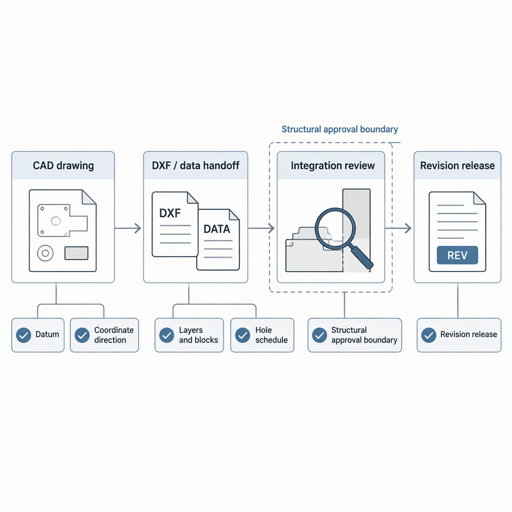
Autodesk explains in About the DXF Format that DXF represents AutoCAD drawing information as tagged data, with group codes indicating the type and meaning of following data for an object or record.
| Buyer question | Why it matters for punching integration | What to ask for |
|---|---|---|
| Will the receiving system read geometry, blocks, layers, or a separate schedule? | DXF is drawing data, so the useful interpretation depends on the receiving workflow. | A written import rule or sample-file review. |
| Are hole marks encoded by layer, block name, text, or table? | DXF block entities can include layer and block-name fields. | A naming convention that the engineering, detailing, and production teams can all follow. |
| Is the DXF only a drawing reference? | Some workflows require manual mapping or intermediate software before punching instructions are created. | Confirmation of the required file package, not just the file extension. |
Organize Layers, Blocks, and Hole Marks Before Import
Use layers, blocks, and hole marks consistently so the same drawing element is not interpreted as geometry by one team and annotation by another.
- Reserve clear layer names for punching geometry, reference geometry, centerlines, dimensions, and notes, because DXF block information can carry layer-name data.
- Use one naming pattern for hole marks, such as a project-defined mark for lap holes, bridging holes, service holes, or connection holes.
- Separate construction lines from punchable geometry so non-punch features are not mistaken for hole centers.
- Keep text callouts and graphical hole symbols aligned with the hole schedule; if one changes, revise the other before release.
- Document whether repeated holes are individual entities, block instances, or schedule-driven locations.
Keep Structural Boundaries Separate From Manufacturing Preparation
Manufacturing teams can prepare clean punching data, but the acceptability of web holes, service holes, extra openings, and revised connection holes belongs with the project’s structural design authority.
For purlin punching patterns, that means the drawing package should record approved hole locations rather than create new structural decisions on the shop floor. If a hole is added, moved, enlarged, or repurposed, route the change through the responsible engineer or project approval process before production.
Ask the Right Integration Questions Before Selecting or Configuring Equipment
Before assuming automatic import, ask how the equipment or software workflow reads drawing data, maps hole types, handles revisions, and separates manufacturing information from design approval.
| Integration question | Good answer to request | Boundary to keep |
|---|---|---|
| Which file information is actually read? | Ask whether the workflow uses DXF geometry, tagged data, layers, blocks, or an external schedule. | Do not assume the file extension proves compatibility. |
| How is the purlin datum selected? | Ask how base points, block insertion, and coordinate direction are interpreted. | Do not let the controller infer the project datum from an unmarked drawing. |
| Who approves changed hole locations? | Ask where structural review is recorded for load-carrying cold-formed members. | Do not treat machine setup as structural approval. |
| Which standard edition governs the project? | Ask the design team to confirm the required edition rather than copying an old drawing note. | Do not mix edition references across projects without review. |
Control Revisions Before the Punching File Reaches Production
Revision control should connect the drawing, hole schedule, file name, datum convention, and approval status so production is not working from an outdated purlin hole pattern.
- Freeze the member mark list and identify which purlins share the same punching pattern.
- Check that the datum and coordinate direction have not changed between revisions.
- Compare the drawing graphics against the hole schedule before releasing a DXF or integration file.
- Send structural changes affecting load-carrying members back to the responsible design process before production release.
- Issue the punching package with a revision number, date, file name, and superseded-file instruction so the shop does not keep two active versions.
Check the Required Standard Edition Instead of Copying an Old Note
Use the standard edition required by the project documents and local adoption, not a note copied from an older detail or unrelated purlin drawing.
The AISI standards listing on Build Using Steel shows multiple cold-formed steel standard editions and supplements, and it identifies examples of superseded standards such as S202-20 superseding S202-15 and S240-20 superseding S240-15.
Final Pre-Integration Checklist
Release the purlin punching package only after the drawing data, datum, layer or block convention, structural approvals, and revision status are clear enough for the receiving workflow to check.
- Datum and coordinate direction are stated on the drawing and match the exported file.
- Layer names, block names, and base-point use are documented where the handoff relies on DXF block or layer information.
- Hole schedule, graphical hole marks, and member marks agree with each other.
- Structural changes to holes in load-carrying cold-formed members have been routed through the responsible design review.
- The project-required standard edition has been confirmed rather than copied from an unrelated legacy note.
- File names and revision notes make superseded punching data easy to remove from production use.
Conclusion
Good purlin punching integration starts with unambiguous drawing information, not with assumptions about a file extension or machine import.
- Define the datum before coordinating hole locations.
- Use consistent layers, blocks, and hole marks.
- Keep structural approval separate from manufacturing data preparation.
- Confirm the applicable standard edition for the project.
FAQs About Purlin Punching Patterns
These questions help buyers and process engineers clarify drawing readiness before purlin punching patterns move into production integration.
Can a DXF file be used directly for purlin punching patterns?
DXF can exchange drawing information, but direct punching use depends on the receiving controller or software workflow and its import rules.
Where should the zero point be placed on a purlin drawing?
Use a single declared project datum or base point and state the coordinate direction so block placement or member reversal does not create a different interpretation.
Should hole sizes and spacings be standardized in the drawing template?
Templates can standardize presentation, but project-specific hole size, spacing, edge distance, reinforcement, and connection rules should come from the approved design documents.
Who approves an added service hole in a purlin web?
Because load-carrying cold-formed members fall within a structural design context, added or changed holes should be approved through the responsible structural design process.
How should layers be named for punching integration?
Use project-defined names that clearly separate punchable geometry, reference geometry, dimensions, notes, and hole marks; DXF block information can carry layer-name data.
Which AISI edition should appear on the drawing?
Use the edition required by the project documents and adopted rules; standards listings show that editions and supplements change over time.
Can one punching pattern be reused for mirrored purlins?
It can be reused only if the drawing package states how mirroring, leading ends, trailing ends, and coordinate direction are handled for that member mark.
What should equipment buyers ask before purchase or configuration?
Ask for the required file package, import rules, datum convention, layer or block mapping, sample-file review process, and revision-control expectations before assuming automatic integration.